8. pnCCD Operation; What to Do While on Shift
To operate the pnCCD camera, this user manual should be followed at all times. If you are in doubt, please contact DOC. The pnCCD elog also has a lot of useful details, tips, pictures and valuable and updated information regarding the hardware, operation and data analysis of pnCCD. Please consider consulting the elog together with this manual.
Follow the instructions given in this section to get the detector ready for data acquisition. For instructions on troubleshooting the problems, see Troubleshooting, and for instructions on the safety measures, see SafetyMeasures.
Depending on the status of the pnCCD detector when you start your shift, your duties may begin differently. The detector may be completely OFF when you begin your shift, or it may already be up and running when you arrive. The following sections explain what you need to know/do.
8.1. pnCCD Is at Room Temperature When You Start Your Shift
In this case, upon arrival in the SQS control room for your shift, please do the following:
If SQS Karabo and pnCCD scenes are already open, skip to the next point. If not, follow the instructions given in
KaraboGui. The Karabo scenes to control pnCCD are (seeKaraboScenes):pnCCD_Main,pnCCD_AcquisitionandpnCCDPowerOverview_New0.
Open the pnCCD elog. Use it to report everything concerning detector commissioning and operation during regular experimental shifts, especially errors, problems, solutions and all general issues.
At the beginning of your shift, start a new elog entry. Make sure the subject describes the entry well.
If you can, go to the hutch and inspect the pnCCD chamber and electronics rack to ensure all the cable connections and the interlock (see
InterlockandinterlockSetup) are set up properly. Also, if there is a window somewhere along the SQS beamline, through which light can penetrate into the beamline, discuss it with the SQS instrument scientists so that they can cover the window as external ambient light will produce a lot of noise on pnCCD images. Furthermore, make sure the light in the clean tent, located inside the hutch, is OFF.Once the hutch is searched and locked, ensure the light in the hutch if turned OFF. This ensures no light penetration in case some window is still not covered.
Ensure the vacuum in the pnCCD chamber is good (\(< 10^{-8}\) mbar). To do this, on the
pnCCD_Mainscene (see Fig. 6.2):- Check the status of
Gauge P_CCD_Low. If it is OFF, turn the gauge ON. Wait for 10 to 15 seconds until the gauge comes online, and reads the actual pressure in the pnCCD chamber on theGauge P_CCD_Lowbox or by looking at theP_CCD_Lowplot. It should be in the \(10^{-8}\) mbar range. If not, consult the SQS beamline scientists. - Make sure both pnCCD turbo pumps (
TP1andTP2) are running at full speed, the valve between them is open (green), and the foreline pressure (P_PRE) is in the low \(10^{-2}\) mbar range. If not, consult the SQS beamline scientists. - The
Chamber 2 Gaugeplot should also show a pressure in the similar range (\(10^{-8}\) mbar). If not, consult the SQS beamline scientists. This is the vacuum in the NQS chamber.
- Check the status of
Once the pnCCD vacuum is checked and you have ensured that the chamber is under good vacuum, you now need to start cooling down the detector. On the cooling section of the
pnCCD_Mainscene:- change both setpoints to \(-50\) (in degC) and each time you change the setpoint, hit the return key on the keyboard to make sure the changes are applied in Karabo. This temperature setpoint is for the Save Operation Mode (see
Modes), which always should be the mode of operation to start with. - make sure both heaters
Rangeis set to 3. This means high range. If this value is zero, the heater is OFF. Settings of 1 and 2 mean low and medium, respectively. These latter heater ranges are not very efficient and should not be used. - turn both
Chiller 1andChiller 2ON. - It takes 5 hours for pnCCD to get to \(-50\) degC from room temperature. You need to wait until the temperatures reach the setpoints and stabilize.
- change both setpoints to \(-50\) (in degC) and each time you change the setpoint, hit the return key on the keyboard to make sure the changes are applied in Karabo. This temperature setpoint is for the Save Operation Mode (see
Note
- On the plots of the cooling section,
Input A,Input B,Input CandInput Dare the top sensor’s, bottom sensor’s, top cold head’s, and bottom cold head’s temperatures, respectively, measured (all in degC) by PT-100 temperature sensors. For each pnCCD module, there is a copper braided piece which couples the corresponding cold head to that module. The length of this copper braid for the top pnCCD sensor is much shorter. Therefore, the thermal coupling between the top cold head and the top pnCCD sensor is the best. That is why, you may observe that even though the bottom cold head may be a few degrees colder than the top cold head, the bottom pnCCD sensor may be hotter than the top one, or it may take longer for the bottom pnCCD sensor to get to its setpoint temperature. - Once each pnCCD module reaches its setpoint temperature, the corresponding heater will come online to stabilize the temperature on the pnCCD module. It will take some minutes for the temperature to stabilize. You may see the heater output percentage to rise initially followed by a gradual drop. This causes the sensor temperature to rise above the setpoint momentarily and gradually gets closer to the setpoint until it is stabilized. Wait for the sensor temperatures to become constant. You can zoom in on the tempertature plots (
Input AandInput B) and ensure they are relatively flat before you carry on to step 12.
Turn both
P_CCD_LowandStage3gauges OFF. The former can be turned OFF via thepnCCD_Mainscene (pnCCD Vesselsubsection of theVacuumsection), while to turn OFF the latter, seeKaraboDevicesVacuum. If these gauges remain ON, you will see a huge noise in the middle of the detector after you bias the pnCCD. Please do not forget to turn them both OFF. Always ask the SQS beamline scientists to turn OFF their beamline LEDs, encoders and gauges. These devices produce noise on pnCCD which will interfere with the experiment.Start the sequencer (see
SequencerCTRL) and change the gain to 1. Make sure that the sequencer console (see Fig. 8.2) reads back the correct gain file. Start with gain 1 so that if there is some faint light ON somewhere (see Fig. 9.4) or if something is going on which causes noise on the detector, the raw image picks it up and you can notice the noise and eliminate it before taking a dark run.Start the FastADC acquisition (see
ADCs). Check the values corresponding toADC1andADC2. They should be changing in theTrigger Timefields on thepnCCD_Mainscene. The values should be around a mean value of 90 ms to 100 ms. Note that both ADCs should be inAcquiringmode.Check the power status of the pnCCD:
- The pnCCD should not be powered at this moment (check the
Powersection of thepnCCD_Mainscene). - The pnCCD power overview (the
pnCCDPowerOverview_New0scene) should look similar to Fig. 8.1. - All voltage values should be reading 0 V.
- The pnCCD should not be powered at this moment (check the

Fig. 8.1 Power overview of the pnCCD when it is OFF. All the voltages and currents should be zero.
- Once the temperature of both pnCCD modules are stable and at the desired value, power up the detector in Save Operation Mode (see
PowerOn).
Note
- You may see strange patterns on the raw and corrected previews while the detector is being biased. Do not be alarmed. This is normal. The raw and corrected images will look different as different parts of the CAMEX/CCD are biased. Once the detector is fully biased, the raw image should look homogeneous and normal. The corrected preview may still look abnormal and will only be OK after you load new dark constants (see
RunControlandDarkRuns). - If after the detector is fully powered ON you see a bright red strip in the middle of the detector, there is some light penetrating through the beamline producing a lot of noise on pnCCD. In this case, see
Light.
- Once the detector is fully biased and the raw data preview (see
RawPreview) shows a homogenious and normal dark image, you can turn ON theP_CCD_Lowgauge for just a very short time only to see if the detector is responsive. You should see that the detector reacts to the light produced by this gauge. You will see a bright intense light in the middle of the detector. Turn this gauge OFF. - Ask the SQS beamline scientists to ensure you can take a dark run. Remind them to close the necessary valves and turn OFF their beamline LEDs, encoders and gauges.
- If you have changed the gain setting, go ahead and also change the gain in the Karabo device that saves the gain in the slow meta data (see
GainSaving). This latter step is of utmost importance. Please do NOT forget to do this step or you run into various troubles later on. - Take a dark run for each pnCCD gain and process them individually to inject the corresponding constants into the calibration database. To do this, follow the instructions given in
DarkRuns. - Check the processed runs’ reports (see
DarkRuns) and ensure everything with the detector and data are OK. If not, seeTroubleshooting. - Ask SQS beamline scientists to see which pnCCD gain is desired. Change the gain (see
SequencerCTRL) if a gain other than 1 is required. - Set the corrected online preview to load the new offset map for the desired pnCCD gain (see
CalibratedPreview). After loading the new constants, the corrected images of the online preview should also look normal and homogenious with most pixels showing a signal around zero ADU. In case of problems, consultTroubleshooting. - Now, you are ready to let the SQS beamline scientists take over and tune the beam. The X-ray beam should never touch the pnCCD. Ask the SQS beamline scientists to reduce the intensity immediately if the readout is saturated to the point that the charge bleeds into nearby pixels. In this case, the ADU value is on the saturation level (see
Saturation) and you see dark red spots or stipes on the corrected images. - Make a note of all the important issues during your shift and post them on the pnCCD elog. Also, take a screen capture of all Karabo scenes and the sequencer’s running window and other important events and attach them to the elog entry.
- If anything happened during your shift and you do not know what to do, call DOC.
- If you need to change the pnCCD mode of operation during your shift, see
ModeChange. Once the detector is power cycled in the desired operation mode, repeat step 13 onward.
Tip
- High gains (such as 1 and 1/4) are used for experiments where the beam intensity is not too high.
- Medium gains (1/16 and 1/64) are used for experiments that require medium-range beam intensities.
- Low gains (1/256, 1/340 and 1/512) are used for experiments where the beam intensity is expected to be high.
8.1.1. What to Do Towards the End of Your Shift
Depending on when your shift ends with respect to the end of the SQS beamtime on that day, you need to choose (depending on the instructions given to you by the SQS beamline scientists) from the following options:
- Leaving the detector as is.
- Leaving the pnCCD fully ON in the Save Operation Mode.
- Powering down the detector and the chillers but heating the detector relatively fast until it comes to room temperature.
- Annealing the pnCCD.
- Turning it OFF completely.
- Turning it OFF for a long shutdown period.
If you need to leave the detector running as is at the end of your shift, please tell the SQS beamline scientists that they need to properly take care of the pnCCD at the end of the SQS beamtime on that day.
If you need to leave the pnCCD fully ON in the Save Operation Mode, you may need to power cycle the detector (see
ModeChange). In this case, do not turn the chillers OFF. Only change the temperature setpoints to \(-50\) degC and make sure the heater ranges are set to 3. Power OFF the detector if it is running in a mode other than theSave Operation Modeand power it back ON in theSave Operation Mode.If you need to power down the detector and heat it to room temperature relatively fast:
- First, make sure the experimenter and the SQS beamline scientists are done with using pnCCD.
- Power OFF the detector (see
PowerOFF). - Once the detector is fully debiased, wait for a few minutes until the automatic power status check confirms that pnCCD is OFF. The message can be seen in the status message window in the
Powersection of thepnCCD_Mainscene. - On the
pnCCD_Mainscene, turn both chillers OFF. - Change the setpoint temperatures (in cooling section) to \(+20\) degC. Make sure both heater ranges are set to 3. This will cause the heaters to come ON at full power and help the temperature rise to the new setpoint quickly. They will turn OFF automatically by the Lake Shore unit once the pnCCD modules reach \(+20\) degC. In rare cases, you may be asked by the SQS beamline scientists to also use the two heaters on the cold heads. If that is the case, follow the instructions given in
ColdHeadHeaters.
If you need to anneal the detector:
- First, make sure the experimenter and the SQS beamline scientists are done with using pnCCD.
- Power OFF the detector (see
PowerOFF). - Once the detector is fully debiased, wait for a few minutes until the automatic power status check confirms that pnCCD is OFF. The message can be seen in the status message window in the
Powersection of thepnCCD_Mainscene. - On the
pnCCD_Mainscene, turn both chillers OFF. - Change the setpoint temperatures (in cooling section) to \(+50\) degC (or to whatever temperature the SQS beamline scientists tell you). Make sure both heater ranges are set to 3. This will cause the heaters to come ON at full power and help the temperature rise to the new setpoint quickly. The detector needs to be heated to above room temperature for at least a few hours for the annealing to be effective.
- Make sure the SQS beamline scientists and the experimenters know that it takes roughly 5 hours for the temperature to reach \(-50\) degC from \(+20\) degC. It will take an additional 2 to 3 hours for the temperature to go down to \(+20\) degC from \(+50\) degC. Also, annealing process takes some 4 to 5 hours at least.
If the detector has to be turned OFF completely at the end of your shift, make sure the experimenter and the SQS beamline scientists are done with using pnCCD. Then, power OFF the detector (see
PowerOFF). Wait for a few minutes until the automatic power status check comes online and esnures the detector is truly OFF. The message can be seen in the status message window in thePowersection of thepnCCD_Mainscene. On thepnCCD_Mainscene, turn both chillers OFF.If the pnCCD is going to be used again the next day, you do not need to stop the acquisition of the FastADCs and/or the sequencer. If however, there is a long period of time (more than 24 hours) between the end of your shift and the start of another shift, where pnCCD is going to be used, you need to:
- Stop both ADCs on the
pnCCD_Mainscene. Make sure their status changes toON(green) fromAcquiring(blue). - Stop the sequencer (see
SequencerCTRL).
- Stop both ADCs on the
Complete and submit the elog entry.
Danger
Do not leave pnCCD biased and unattended for a long period of time. It is OK to leave it ON over a night but it must be left in the Save Operation Mode.
8.2. pnCCD Is Already Running When You Start Your Shift
If the detector is already running (cold and fully biased) upon your arrival in the SQS control room for your shift, please do the following:
If SQS Karabo and pnCCD scenes are already open, skip to the next point. If not, follow the instructions given in
KaraboGui. The Karabo projects to control pnCCD are (seeKaraboScenes):pnCCD_Main,pnCCD_AcquisitionandpnCCDPowerOverview_New0.
Open the pnCCD elog. Use it to report everything concerning detector commissioning and operation during regular experimental shifts, especially errors, problems, solutions and all general issues.
At the beginning of your shift, start a new elog entry. Make sure the subject describes the entry well.
Ensure the vacuum in the pnCCD chamber is good (\(< 10^{-8}\) mbar). To do this, on the
pnCCD_Mainscene (see Fig. 6.2):If the detector is ON, the
P_CCD_Lowgauge should be OFF, and thus theP_CCD_Lowplot should show a straight line at 0 (and the value in theGauge P_CCD_Lowbox is in \(10^{-10}\) range).If the detector is ON and the experiment is in progress (for example, in middle of a shift), the vacuum should already be OK. Check the elog to ensure an accident has not happened. Alternatively, one can:
- ask the SQS beamline scientists.
- whenever the detector is idle and is not in use, turn the
P_CCD_Lowgauge ON momentarily and ensure the vacuum in the chamber is OK. While the detector is ON and if you turn ON theP_CCD_Lowgauge, you will see a bright intense red strip in the middle of the detector. Do not be alarmed. This is produced by theP_CCD_Lowgauge. Do not forget to turn the P_CCD_Low gauge OFF. - check the NQS vacuum: the value in the
Gauge Chamber_2box or its corresponding plot should give you the NQS vacuum, which is an approximate estimate of the pressure in the pnCCD chamber. This gauge remains ON even if the pnCCD is in operation and has no influence on the pnCCD. TheGauge Stage3status should be OFF if the pnCCD is in operation because this gauge will produce noise on the pnCCD images. If the detector is idle, one can also turn this gauge ON (seeKaraboDevices) to read the NQS vacuum, which should be roughly the same as that of the pnCCD chamber. Do not forget to turn the Stage3 gauge OFF.
On the
pnCCD_Mainscene, make sure both pnCCD turbo pumps (TP1andTP2) are running at full speed, the valve between them is open (green), and the foreline pressure (P_PRE) is in the low \(10^{-2}\) mbar range.If the vacuum in the pnCCD chamber is not good (\(> 10^{-7}\) mbar), inform a member of the SQS.
Check the temperatures at various locations (see the
Input A,Input B,Input CandInput D(which are the temperatures of the top and bottom pnCCD sensors and the corresponding top and bottom cold heads, respectively) plots of the cooling section in thepnCCD_Mainscene). They should be stable and close to the setpoints.On the
pnCCD_Mainscene, check the power status of the pnCCD:- The pnCCD should be powered. The boolean state indicator near
Power Onbutton should be green,POWER PROC Statusshould beONand green, andMPOD Statusshould beActive. If the automatic power status check is operating while you look atPOWER PROC Status, you may see it becoming blue and it may readCHANGING. This is OK. Wait a few seconds to ensure that the power status check is successfully done. Then, in the status message window found in thePowersection on thepnCCD_Mainscene, you should see “PNCCD is on.” - The pnCCD power overview should look similar to Fig. 6.3 except the actual voltages may be different depending on the operation mode.
- The pnCCD should be powered. The boolean state indicator near
If the sequencer control software is not running, ask the SQS beamline scientists which gain is desired and start the sequencer using the instruction given on
SequencerCTRL. Make sure that the sequencer console (see Fig. 8.2) reads back the correct gain file. If you have the time, start with gain 1 so that if there is some faint light ON somewhere (see Fig. 9.4) or if something is going on which causes noise on the detector, the raw image picks it up and you can notice the noise and eliminate it before taking a dark run. Also, it is always a good idea to take a dark run with gain 1 in addition to the desired gain. Gain 1 dark report can be used to troubleshoot a few things later on (seeannealing).Start the FastADC acquisition (see
ADCs). Check the values corresponding toADC1andADC2. They should be changing in theTrigger Timefields on thepnCCD_Mainscene. The values should be around a mean value of 90 ms to 100 ms. Note that both ADCs should be inAcquiringmode.Ask the SQS beamline scientists to ensure you can take a dark run. Remind them to close the necessary valves and turn OFF their beamline LEDs, encoders and gauges.
If you have changed the gain setting, go ahead and also change the gain in the Karabo device that saves the gain in the slow meta data (see
GainSaving). This latter step is of utmost importance. Please do NOT forget to do this step or you run into various troubles later on.Take a dark run for each pnCCD gain (if time allows) and process them individually to inject the corresponding constants into the calibration database. To do this, follow the instructions given in
DarkRuns. If time is tight, take a dark run for the desired gain(s) and process them.Check the processed runs’ reports (see
DarkRuns) and ensure everything with the detector and data are OK. If not, seeTroubleshooting.Set the corrected online preview to load the new offset map for the desired pnCCD gain (see
CalibratedPreview). After loading the new constants, the corrected images of the online preview should also look normal and homogenious with most pixels showing a signal around 0 ADU. In case of problems, consultTroubleshooting.Now, you are ready to let the SQS beamline scientists and the experimenters to take over. The X-ray beam should never touch the pnCCD. Ask the SQS beamline scientists to reduce the intensity immediately if the readout is saturated to the point that the charge bleeds into nearby pixels. In this case, the ADU value is on the saturation level (see
Saturation) and you see dark red spots or stipes on the corrected images.Make a note of all the important issues during your shift and post them on the pnCCD elog. Also, take a screen capture of all Karabo scenes and the sequencer’s running window and other important events and attach them to the elog entry.
If anything happened during your shift and you do not know what to do, call DOC.
If you need to change the pnCCD mode of operation during your shift, see
ModeChange. Once the detector is power cycled in the desired operation mode, repeat step 9 onward.Towards the end of your shift, you need to prepare yourself for your last duties. These are mentioned in
EndofShift.
Tip
- High gains (such as 1 and 1/4) are used for experiments where the beam intensity is not too high.
- Medium gains (1/16 and 1/64) are used for experiments that require medium-range beam intensities.
- Low gains (1/256, 1/340 and 1/512) are used for experiments where the beam intensity is expected to be high.
8.3. Operating the pnCCD Front-End Electronics
To be able to operate these, the cables should all be connected properly (see CCcables) and the interlock should be set up properly (see Interlock and interlockSetup). If these are already done prior to the start of your shift, all you have to do is to control the sequencer, START/STOP the ADCs acquisition, and maybe change the CLEAR and START trigger times. The next subsections explain these steps.
8.3.1. Sequencer Control
To start the sequencer program:
Open a new terminal on the control computer in the SQS control room. Make sure
sqsopis logged in. If not, you need to log into the SQS control PC. Connect to the sequencer control PC via executing the following command:ssh pnccd(at)192[dot]168[dot]158[dot]107
Tip
- The sequencer control PC can only be accessed via the SQS control PC. If you want to have access to the sequencer from a computer other than SQS control PC, you need to first log into the latter using the
sqsopuser.
Change to the directory where
seqCtrlexecutable file is located:cd /home/pnccd/SEQ-NEW/binStart the sequencer program with the following command:
./seqCtrl -n XFEL_XXX
where XFEL_XXX is the desired timing configuration file, and XXX defines the desired pnCCD gain: valid values are 001, 004, 016, 064, 256, 340 and 512. These values correspond to the actual gains of 1 (highest gain), 1/4, 1/16, 1/64, 1/256, 1/340 and 1/512 (lowest gain), respectively.
Note
- High gains (such as 1 and 1/4) are used for experiments where the beam intensity is low.
- Medium gains (1/16 and 1/64) are used for experiments that require medium-range beam intensities.
- Low gains (1/256, 1/340 and 1/512) are used for experiments where the beam intensity is expected to be high.
Now, the terminal should look like Fig. 8.2. Make sure that the sequencer console (see Fig. 8.2) reads back the correct gain file. The two numbers at the buttom right of the sequencer console (labelled as
ReadandClear) count the number of trains/frames. If these numbers are missing, on the sequencer console, typeHand then the two counters should appear. If the sequencer is up and running, these numbers should increase incrementally. If only one counter is active, seeOneCounter. To clear the counters, click on the sequencer console and typeK. After this, you should see the counters start counting again from 0. This is a good way to count 500 trains for a dark run.If you have changed the gain setting, go ahead and also change the gain in the Karabo device that saves the gain in the slow meta data (see
GainSaving). This latter step is of utmost importance. Please do NOT forget to do this step or you run into various troubles later on.To stop the sequencer:
- Click on the sequencer console and type
S. This will stop the counters. It is OK to entirely skip this step and just do the next step. - Then type
Q. This will quit and bring you back to the original linux terminal logged onto the sequencer control PC. - If you want to change the gain, repeat step 3 mentioned above with the new gain.
- If you want to quit using the sequencer completely, go on to step 7.
- Click on the sequencer console and type
To stop the sequencer for a long period of time, e.g., after the SQS beamtime with pnCCD is finished:
- Type
Qon the sequencer console. This will quit and bring you back to the original linux terminal logged onto the sequencer control PC. - Type
exitto exit from the sequencer control PC and go back to the SQS control PC withsqsopuser logged on. - Type
exitagain to close the terminal.
- Type
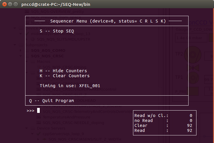
Fig. 8.2 The sequencer console. The two numbers at the buttom right count the number of trains/frames. If the sequencer is up and running, these numbers should increase incrementally. If only one counter is active, see OneCounter. If both these numbers are missing, on the sequencer console, type H and then the two counters should appear.
8.3.2. Starting the Acquisition of FastADC Digitizers
The FastADC digitizers could acquire data independent of the pnCCD decetor. Even if the detector is completely OFF, you could start their acquisition; however, they would only show noise. The ADCs could be running before one powers up the detector. In this case, the raw data preview will change and may show dramatic and sometimes strange patterns as different parts of the detector are biased. Once the pnCCD is fully biased, you should expect to see a normal homogenious image (in the absence of any ambient light).
In order to start the acquisition of the FastADC digitizers:
- The cables need to be connected (see
ADCCablesExplained).- One has to first start the sequencer (see
SequencerCTRL). While the sequencer is stopped, no signals are sent until it is restarted AND the next readout trigger arrives. Without the sequencer running, the FastADCs will not function properly and seem to be stuck if you start their acquisition (seeADCTroubleshooting).- Make sure the
FMT-0status (on thepnCCD_Mainscene) isActiveand green. If not, seeFormatter.- Once the sequencer is started, go to the
pnCCD_Mainscene. On the bottom right of the scene, click onStartbuttons corresponding toADC1(top pnCCD sensor) andADC2(bottom pnCCD sensor).- At this point, check the values corresponding to
ADC1andADC2. They should be changing in theTrigger Timefields on thepnCCD_Mainscene. The values should be around a mean value of 90 ms to 100 ms. Note that both ADCs should be inAcquiringmode.- You should also verify that the
Train IDfield corresponding toADC1andADC2keeps changing.- The
Ratefield should be around 10 Hz.- The
Latencyshould be a number between 80 to 100 ms. This is the small time difference betweenADC1andADC2.
To stop the acquisition of the FastADC digitizers, click on the Stop buttons corresponding to ADC1 (top pnCCD sensor) and ADC2.
8.4. Changing Trigger Times:
The clock and control triggers are explained in clockAndControl. If you need to change the SEQUENCER CLEAR TRIGGER and SEQUENCER START TRIGGER signals provided by the clock and control system:
Go to the
DET_LAB_SYS/TSYS/UTC-1-S2Karabo device (see Fig. 8.3). You can find this device by searching its name inSystem Topology.Scroll down until you find
FRONT TRG 1.Expand the
FRONT TRG 1menu.The entry for
Delayinput is the SEQUENCER CLEAR TRIGGER time that you may want to change. Note that this number in Karabo is in units of clock cycle.To change time in units of milliseconds to time in units of clock cycle, use:
$$ \frac{T \times 10^{6}}{9.23} = t, $$
whereTis the desired trigger time (in ms),tis the time in clock cycle shown as theDelayinput of theFRONT TRG 1orFRONT TRG 2, and \(10^{+6}\) converts ms to ns.
- Similarly, change the
Delayinput ofFRONT TRG 2. This is the SEQUENCER START TRIGGER time that you may want to change. Note that this number in Karabo is also in units of clock cycle. To convert your desired start time in ms to clock cycle, use the equation provided above.- Click on
Shutdown instancebutton on the left bottom corner of theConfiguration Editorto shutdown the Karabo device.- Save your changes in Karabo by clicking on the
savemenu on the top left corner of Karabo.- Reinstantiate the device by clicking on
Instantiatebutton on the left bottom corner of theConfiguration Editor.
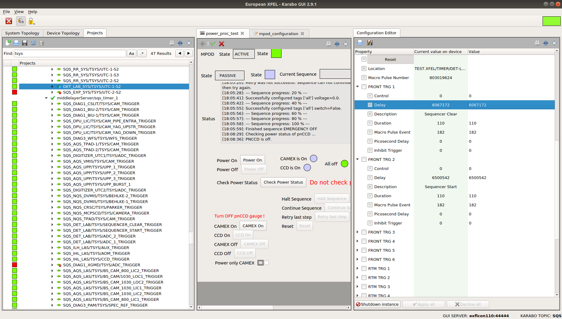
Fig. 8.3 The Karabo device with which one can change the SEQUENCER CLEAR TRIGGER and SEQUENCER START TRIGGER timing signals provided by the clock and control system.
Warning
- The SEQUENCER CLEAR TRIGGER time (in ms) must be a smaller number than the SEQUENCER START TRIGGER time (in ms), i.e., the SEQUENCER CLEAR TRIGGER signal must arrive first in time. Therefore, the SEQUENCER START TRIGGER time in clock cycles must be a larger number than the SEQUENCER CLEAR TRIGGER time in clock cycles.
8.5. Saving the pnCCD Gain Setting
The pnCCD gain setting has to also be manually updated in Karabo according to the sequencer settings. This is because currently, the sequencer does not have any associated Karabo device. Therefore, the gain setting configured by the sequencer will not be automatically saved in the slow meta data unless you manually change the gain setting in the SQS_NQS_PNCCD1MP/MDL/DAQ_GAIN middle layer Karabo device (see KaraboGain and Fig. 8.4). This device is a generic DAQ device which passes the pnCCD gain setting to the pnCCD data aggregators to be recorded into a data file using the DAQ system. To do so:
- Everytime the gain setting of the pnCCD is changed via changing the sequencer timing configuration file (see
SequencerCTRL), you need to do the following ONLY IF YOU WANT TO TAKE A RUN. It does not matter whether or not, the run is dark. If you want to save data and take a run, you have to follow the steps below.- Find the
SQS_NQS_PNCCD1MP/MDL/DAQ_GAINKarabo device under theSQS_PNCCDsubproject, which is a subproject under theAMAINproject of SQS Karabo topic.- Shutdown the aforementioned device (from the
Configuration Editorwindow).- Scroll down on the
Configuration Editorof the device and click on theTable Elementbutton in front of theEvaluated properties.- Change the gain value in the
Evaluated Formulafield. Click on theOKbutton (see Fig. 8.5).- Click on the
Apply Allbutton if this button exist on the bottom of theConfiguration Editorof the Karabo device. If the button does not exist, just skip this step.- Instantiate the device.
- Click on the
Startbutton on the bottom of theConfiguration Editorof the Karabo device. This step is VERY important. Without this step, the new gain will not be saved.- Make sure the
PNCCD_Gainfield on the very end of theConfiguration Editorof the Karabo device is reading the correct gain setting. If not, you may have forgotten to click onStart(see above).

Fig. 8.4 The Karabo device with which one can save the pnCCD gain setting in the slow meta data.
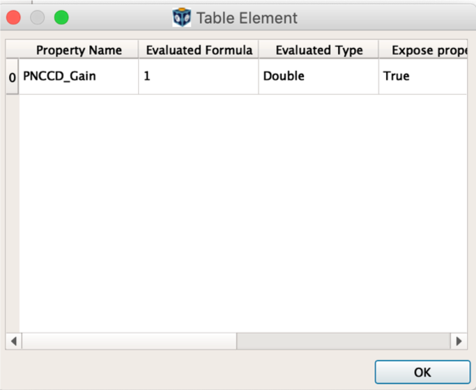
Fig. 8.5 The pnCCD gain setting needs to be saved manually each time the gain is changed via the sequencer.
Now, the pnCCD gain setting is properly saved in the slow meta data once you start a run. If you forget to carry out the above steps, the wrong gain setting will be saved, which will prevent you from loading correct dark constants into the online calibration pipeline. The gain will be saved in the raw data with a value the same as that from the last time someone has properly performed these steps. DO NOT FORGET TO CARRY OUT THESE FEW STEPS TO SAVE THE PNCCD GAIN SETTING.
8.6. pnCCD Power
pnCCD has 4 modes of operation (see Table 8.1). Each mode is intended for a different purpose. These modes are described in a yaml file, which is loaded onto the SQS_NQS_PNCCD1MP/MCPS/POWER_PROC karabo device (see MPODDevices).
The pnCCD modes of operation are:
Normal: This is the mode of operation for the intermediate dynamic range used for many X-ray bunches. The voltages of the top and bottom modules for this mode are \(-400\) V. In this mode of operation, the pnCCD outputs the most heat (approximately 14 W [1]). Due to less efficient thermal coupling between the bottom pnCCD sensor and its corresponding cold head, the Lake Shore unit is not capable of maintaining \(-30\) degC temperature on the bottom pnCCD sensor. Thus, the temperature of the bottom sensor takes a long time to stabilize and even after it stabilizes, it may be hotter than the top sensor by up to 8 degrees. Therefore, you need to cool down the detector to \(-30\) degC on the top sensor and \(-40\) degC on the bottom sensor before you could use this mode of operation. The voltages of the 88 voltage channels related to this mode of operation are shown in Fig. 8.6.Save: Used for tunning the beam through the pnCCD and during the stray light optimization. If you are turning the pnCCD ON after it was OFF for some time, or if you are starting a new user shift, always use this mode. Also, this is the only operation mode, which is safe to use to leave the detector fully biased and unattended for 12 hours in between the SQS daily/nightly shifts. The voltages of the top and bottom modules for this mode are \(-270\) V. You need to cool down the detector to \(-50\) degC before you could use this mode of operation. The voltages of the 88 voltage channels related to this mode of operation are shown in Fig. 6.3.High Dynamic Range: High dynamic range mode is used for flat field measurements. The voltages of the top and bottom modules for this mode are \(-470\) V. You need to cool down the detector to \(-30\) degC before you could use this mode of operation. The voltages of the 88 voltage channels related to this mode of operation are shown in Fig. 8.7.CAMEX Only: This mode is used during early stages of commissioning and for tests such as electronics tests with the FastADC digitizers without using the full detector. The CCD modules will not be powerd on in this mode. Only CAMEX modules will be biased. Therefore, both voltages of the modules labelled asbackon Fig. 6.3 will be 0 V if this mode is used since these aforementioned voltages are the HV of the top and bottom CCD modules, which will not be powered in this mode. The pnCCD does not need to be cooled down if this mode of operation is going to be used. This mode can be used with the detector vented and at room temperature. The voltages of the 88 voltage channels related to this mode of operation are shown in Fig. 8.8.
| Operation Mode | Top/Bottom Sensors Voltages | Temperature Setpoints for the pnCCD Sensors | Actual Temperatures for the pnCCD Sensors |
| Normal | \(-400\) V | \(-30\) degC (top), \(-40\) degC (bottom) | \(-30\) degC (top), \(-26\) degC (bottom) |
| Save | \(-270\) V | \(-50\) degC (top), \(-50\) degC (bottom) | \(-50\) degC (top), \(-50\) degC (bottom) |
| High Dynamic Range | \(-470\) V | \(-30\) degC (top), \(-30\) degC (bottom) | \(-30\) degC (top), \(-30\) degC (bottom) |
| CANEX Only | CCD is not powered | No cooling is necessary | No cooling is necessary |
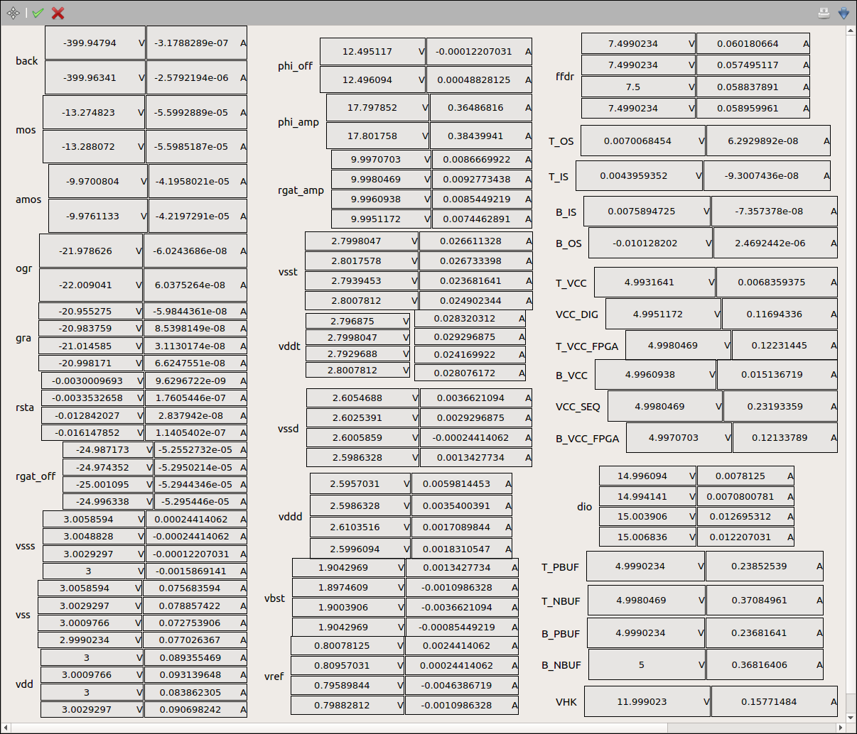
Fig. 8.6 The voltages/currents of the 88 voltage channels of pnCCD if Normal mode of operation is chosen. This screen capture was taken prior to making changes to the pnCCDPowerOverview_New0 scene. This is why the scene looks different from that of Fig. 6.3.
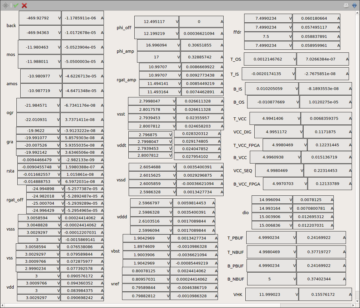
Fig. 8.7 The voltages/currents of the 88 voltage channels of pnCCD if High Dynamic Range mode of operation is chosen. This screen capture was taken prior to making changes to the pnCCDPowerOverview_New0 scene. This is why the scene looks different from that of Fig. 6.3.
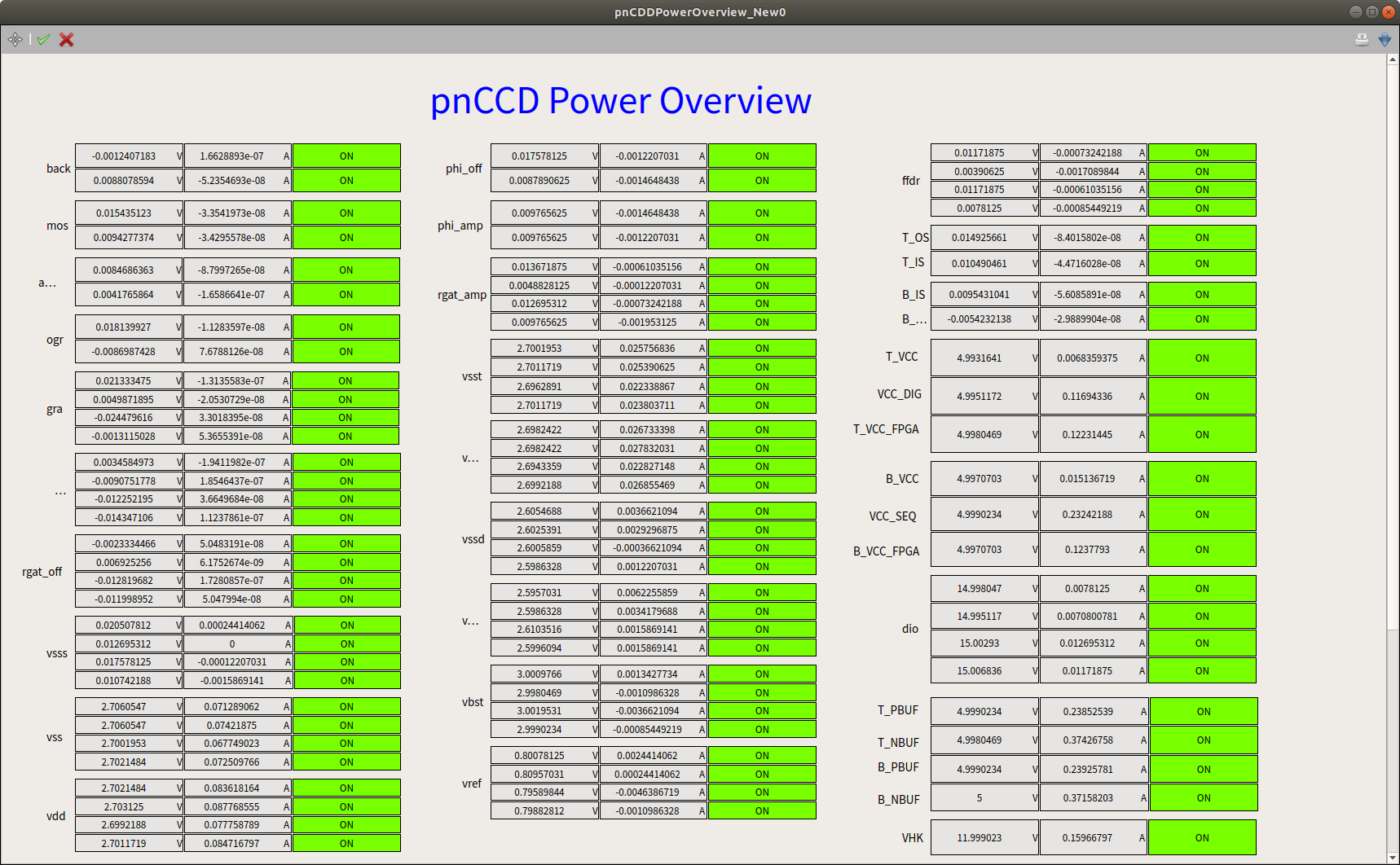
Fig. 8.8 The voltages/currents of the 88 voltage channels of pnCCD if CAMEX Only mode of operation is chosen.
The following subsections will describe how to power up/down the pnCCD and how to change the operation mode while the detector is running.
8.6.1. Powering ON the pnCCD
Ensure that the vacuum in the detector chamber is OK (in the \(10^{-8}\) mbar range). Ensure the top and bottom pnCCD modules’ temperatures have reached the desired setpoints (see Table 8.1) and are stable (zoom in on inputA and inputB plots on the pnCCD_Main scene to enusre the temperatures are flat). You can now start powering up the detector. To do this:
- Do not leave the detector unattended while powering up. An error may occur and you need to act immediately.
- Go to the
Powersection of thepnCCD_Mainscene (see Fig. 6.2) and check to ensure thePOWER PROC Statusis in thePASSIVEstate and that the pnCCD is OFF, which means the boolean state indicator beside thePower Offbutton is green. The status message window on thepnCCD_Mainscene should print “PNCCD is off”. - Go to
Operation Modeof thepnCCD_Mainscene. Change the mode to the desired mode and hitEnteron the keyboard to make the change effective. Alternatively, theSQS_NQS_PNCCD1MP/MCPS/POWER_PROCKarabo device (seeMPODDevices) is the place where mode of operation can be changed. Choose the desired operation mode from theOperation Modedrop down menu on the latter Karabo device (see Fig. 8.9) and push enter to save the choice in Karabo. - If the automatic power status check comes online, the
POWER PROC Statuschanges toCHANGINGstate. If that is the case, wait until the power status check is finished and thePOWER PROC Statuschanges toPASSIVEstate. The status message window on thepnCCD_Mainscene should print “PNCCD is off”. - Press the
Power Onbutton to start the powering up sequence of the detector. While thePower Onscript is running, different voltages will be turned on. Feedback about the status of the procedure is provided in the status message window. - Follow the procedure closely and verify that the indicated voltages are changing accordingly by looking at the
pnCCDPowerOverview_New0scene (see Fig. 6.3) and comparing the voltages to what is written out in the status message window. If you get any error, seePowerIssues. - The procedure will take about 12 to 15 minutes to finish. Wait till all the powering steps are done properly.
- At the end of the procedure, the status message window will show the message “Finished sequence pnCCD is ON”. In addition, the boolean state indicator beside the
Power Onbutton should go green. - Check the voltage values shown in the
pnCCDPowerOverview_New0scene against Fig. 6.3, Fig. 8.6, Fig. 8.7, or Fig. 8.8 (depending on the desired mode). The voltage values should be similar. - You have now successfully powered up the pnCCD.
- Due to safety reasons, one cannot change the operation mode while the detector is ON. If you would like to do this, see
ModeChange.

Fig. 8.9 Choose the desired mode of operation (via the related Karabo device) before your power up the pnCCD detector.
8.6.2. Powering OFF the pnCCD
- Do not leave the detector unattended while powering up. An error may occur and you need to act immediately.
- Make sure the experimenters and the SQS beamline scientists are done using pnCCD and a run is not in progress.
- Go to the
Powersection of thepnCCD_Mainscene (see Fig. 6.2). - Click on the
Power Offbutton to start the powering down sequence of the detector. While thePower Offscript is running, different voltages will be turned off. Feedback about the status of the procedure is provided in the status message window. Follow this carefully and verify that the indicated voltages are changing in thepnCCDPowerOverview_New0scene (see Fig. 6.3). - The procedure will take about 12 to 15 minutes to finish. Wait till all the powering down steps are performed properly. If you get any error, see
PowerIssues. - At the end of the procedure, the status message window will show the message “Finished sequence pnCCD is OFF”. In addition, the boolean state indicator beside the
Power Offbutton should go green. - Check the voltage values shown in the
pnCCDPowerOverview_New0scene. All the voltage values should be 0 V and all currents should be 0 A. - You have now successfully turned the pnCCD off.
8.6.3. Changing the pnCCD Operation Mode
Due to safety reasons, one cannot change the operation mode while the detector is ON (fully biased). To change the mode of operation while the detector is already up and running (fully biased):
- Make sure the experimenters and the SQS beamline scientists are done using pnCCD and a run is not in progress.
- The pnCCD should be first turned OFF (see
PowerOFF).- Wait for a few minutes to check that the automatic power status check verifies that pnCCD is OFF.
- Change the temperature setpoints (see
Chillers) according to Table 8.1.- Wait until both pnCCD modules reach the desired temperature setpoints and the temperatures are stable.
- Follow the instructions given in
PowerOn.
8.7. Operating pnCCD Chillers and Heaters
In the cooling section of the pnCCD_Main scene, there are two temperature plots. InputA, InputB, InputC and InputD correspond to the temperature sensors located at top and bottom hemispheres of the pnCCD, and the cryogenic cold heads for the top and bottom hemispheres of the detector, respectively. All temperatures in the graphs are in degC. The values are given in degC and degK in the Heater and Cold Head fields on the pnCCD_Main scene.
The two chillers (see Fig. 4.14) correspond to the two pnCCD modules (top and bottom). They can be turned ON/OFF directly from the pnCCD_Main scene (see Fig. 6.2) provided that the interlock is set properly (see Interlock and ChillersCablespnCCD). If the chillers are interlocked, their status indicators in the pnCCD_Main scene will be magenta color and they cannot be turned ON (see ChillerProblem). When you turn the chillers ON/OFF via Karabo, the chillers’ control unit (see Fig. 4.15) will turn the chillers ON/OFF. One can also turn the chillers ON/OFF (provided that they are not interlocked) manually using the ON/OFF switches on the chillers’ control unit (see Fig. 4.15).
Once the temperatures of the two pnCCD sensors go lower than the corresponding heater setpoints, the heaters come online and start outputting heat, which is shown by a percentage value in the Heater field on the pnCCD_Main scene. The heater percentage should increase in order to compensate the cooling power and maintain the desired temperature value. When the detector is biased, it also produces heat (particularly if the mode of operation is Normal). For this reason and to save time, it is best to wait till the desired temperature is reached before operating the detector. Otherwise, you may need to wait much longer for the temperatures to reach the desired values and become stable.
The pnCCD is calibrated and commissioned at particular temperatures and voltages. These are given in Table 8.1. Please do not choose any temperature setpoints outside what is provided here or you may need to calibrate the detector first.
The Lake Shore unit can also be operated manually. Please consult the Lake Shore 336 manual.
The heater range should always be selected as 3 (High) in the Range field on the pnCCD_Main scene. Heater Range of 1 (low) and 2 (medium) are not efficient enough. Heater Range of zero indicates the heater is OFF.
8.7.1. Turning ON the Cold Head Heaters
There is an auxillary power supply on the pnCCD electronics rack (see Fig. 8.10) with which we can provide power to the two cold heads’ heaters. This device is not connected to Karabo yet; and therefore, if required, one has to do the following manually by entering the SQS hutch to perform the following tasks on the Lake Shore unit as well as on the aforementioned auxillary power supply:
- Turn ON heaters 3 and 4 on the Lake Shore unit. These two heaters are also not implemented in Karabo yet. Instructions regarding this step can be found in Lake Shore 336 manual.
- Turn ON both outputs on the auxillary power supply shown on Fig. 8.10 by flipping both the power switches to 1.
- Very slowly increase the current (using the current knob) and go back to the control room and check the cold head temperatures shown as
inputC(for the top pnCCD cold head) andinputD(for the bottom pnCCD cold head) thepnCCD_Mainscene (see Fig. 6.2). Try to avoid increasing the cold heads’ temperatures too fast. Try to maintain a steady temperature increase on the heaters by adjusting the currents as needed.- When the cold heads’ temperatures are at the desired levels, turn the currents on this power supply back to zero and turn the power supply OFF (both sides).
- Turn OFF heaters 3 and 4 on the Lake Shore unit.
Danger
- Note that turning off the chillers and turning on the heaters for the cold heads will cause the pressure to go up in the pnCCD chamber. If these heaters are heating the cold heads too much and/or too fast, the vacuum interlock may be triggered, which then closes the valve on the pnCCD chamber and turns OFF the MPOD power supply and the chillers. This is a very dangerous situation because currently if the MPOD system is shutdown even though the UPS is online, the detector will be seriously damaged. This is due to the fact that the MPOD controller card is unable to sequencially turn OFF LV cards, and thus the detector will be shutdown without following the necessary power down sequence.
- Make sure you are very careful with the current settings (on the auxillary power supply) of the cold heads’ heaters to avoid the aforementioned issue.
- For this reason, turn OFF pnCCD first before turning the cold heads’ heaters ON.

Fig. 8.10 The auxillary power supply for heaters 3 and 4 (small LEDs on the front of the Lake Shore unit), which are associated with heaters C and D, in Karabo, used to heat the pnCCD cold heads if necessary.
8.7.2. What happens if Chillers Stay ON while pnCCD if OFF?
If the detector is not biased but the heaters and the chillers stay ON, the cold heads reach temperatures between \(-150\) degC and \(-160\) degC. The top sensor will reach \(-50\) degC, while the bottom sensor will reach \(-40\) degC without the heat output from the detector. This is OK with the detector and it will not be damaged. But once the detector is biased, it will take approximately one hour for the top sensor to reach \(-30\) degC if its setpoint is changed to \(-30\) degC. If the mode of operation is not set to Normal, the bottom sensor will reach the same temperature about an hour later. If the operation mode is chosen to be Normal, the bottom temperature will not be stable at \(-30\) degC with the same setpoint. You need to change the bottom setpoint to \(-40\) degC and even then, the bottom temperature stabilizes at \(-26\) degC or so.
PNSensor recommends that if the detector has to stay OFF while the chillers and heaters are all ON, keep the temperature setpoints at \(-50\) degC and \(-40\) degC on the top and bottom sensors, respectively. This way, you will save some time in changing the setpoints later on when the detector is powered up.
8.8. Processing Dark Runs
- Following the instructions given in
RunControl,ShiftandMidShift, start a dark run. Make sure you have acquired approximately 500 images, i.e., approximately 1 minute of data taking. Stop the dark run after a minute or 500 trains. - After taking a dark run for each gain setting, log into Meta Data Catalog. Click on Proposals link on the top right hand side. Find your desired proposal. If you cannot find the current proposal, make sure the SQS beamline scientists have given you the permission to access it. Open the Runs page. There you should see the run numbers corresponding to the dark runs you just took. It might take a few minutes for the runs to appear on the list (you will also need to reload the page manually to see the new runs). If the dark runs you took were all OK, change the Data Assessment to Good (if you cannot do this step, you do not have the right permissions for this proposal and need to ask a member of the SQS group). At this stage, the data are migrated to Maxwell cluster.
To process the dark runs and inject the dark constants to the calibration database, use Meta Data Catalog as instructed below:
- Go to the proposal of interest on the
Meta Data Catalog.- Click on
Calibration Constants Betamenu button.
- Make sure the following fields and labels are inputted correctly:
Detector: selectSQS_NQS_PNCCD1MP.Detector Units: selectPNCCD01.Operation Mode: selectStandard Operation.Run Number(s): choose the correct dark run number for processing. This run has to be a dark run.Description: you can leave this field blank or write a proper description.- Click on the
Requestbutton.- Once you refresh the page, there will be an entry under
Dark runs requestsappearing (see Fig. 8.11). The status field should be blue and should showIn Progress. Keep refreshing the page until the status field turns green and showFinished. At this point, you can download the pdf output only from a computer that is not on the controls network. Note that the pdf file can not be accessed from the SQS control PC and you need to be on the DESY/XFEL network. Otherwise, the file is inaccessible. This pdf file appears underExternal resourcesfield. Please make sure you open the pdf file and look through to ensure there are no errors. If the status field remains onIn Progressfor more than 5 minutes, please be patient. Sometimes Maxwell cluster becomes slow and it may take a much longer time to process the run. If the status never changes toFinishedand the run seems to be stuck, seeTroubleshooting.- The blue button with an eye logo (
See all details) can be clicked to get information on various things such as where the dark constants (NoiseMap, OffsetMap and BadPixelsMap) are saved. This is in case you need to have access to these.h5files for Karabo bridge.- Make a note of
Creation timefrom the pdf file (found on page number 5 of the pdf output). This is the creation time for the dark constants of interest. Once you load the dark constants in the online preview (seeCalibratedPreview), you want to make sure the constants that are recently loaded have the sameCreation timeas the dark run with the desired gain. Furthermore, check the very end of the pdf report to ensure the constants are injected into the calibration database successfully and make sure they have the correct gain setting, bias voltage and temperature setting (in Kelvin). The bias voltage and temperature settings that you see are taken from the top pnCCD module. Those of the bottom module are not currently taken into account in the calibration database. However, they are still saved in the slow meta data for the bottom pnCCD module. #. Once the dark runs are analyzed and the calibration constants are injected into the calibration database, you can setup the calibrated preview (seeCalibratedPreview) or calibrate/recalibrate acquired data (see next section).- Consult
Troubleshootingto solve problems that may occur. If you cannot solve the issue at hand, call DOC or Calibration OCD.

8.9. Calibrating/Recalibrating Acquired Data
- You can find instructions on the webservice-based Calibration using the Metadata Catalogue Interface.
- Log into Metadata Catalog. Click on Proposals link on the top right hand side. Find your desired proposal. If you cannot find the current proposal, make sure the SQS beamline scientists have given you the permission to access it. Open the Runs page. Do NOT click on the blue button with
Runsin the middle of the button and some horizontal lines on its left side. Instead, click onRunsmenu to the left ofTeammenu (see Fig. 9.1). There you should see the run numbers corresponding to the runs you want to calibrate. It might take a few minutes for the runs to appear on the list (you will also need to reload the page manually to see the new runs). If the runs were all OK, change the Data Assessment to Good (if you cannot do this step, you do not have the right permissions for this proposal and need to ask a member of the SQS group). At this stage, the data are migrated to Maxwell cluster. - There is a button labelled as
Calibration. Click on it. The button changes to(Re)calibrate?status. Click again. This will initiate a fairly long process of calibrating/recalibrating the run. If the button does not work, seeCalibratingProblems. - After the web service-based calibration process is over, if you look at the
proc/folder of the desired proposal, you will see many files per each raw file per each data aggregator. Those files whose names start withCORRcontain corrected data in the “image” array, where the type of corrections depend on the experimenter’s request.
8.10. Online Preview
8.10.1. Raw Preview
The Raw Image panel in the pnCCD_Acquisition scene shows a preview of the raw data acquired by the pnCCD detector. This image is not corrected at all. In general, you should set the limits of the z-axis (color scale in ADU) of this image according to the pnCCD gain settings. Also, be aware that the dark offset is about 10000 ADU.
From the pnCCD calibration data using Al-fluorescence (with \(E_{\gamma}\) = 1.5 keV) at 1.6-keV photon energy, we have the following approximate keV to ADU calibration:
| pnCCD Gain | ADU Value Corresponding to \(E_{\gamma}\) = 1.5 keV |
| 1 | 5730.4 \(\pm\) 0.3 |
| 1/4 | 1434.4 \(\pm\) 1.2 |
| 1/16 | 382.4 \(\pm\) 0.1 |
| 1/64 | 99.4 \(\pm\) 0.1 |
| 1/256 | 23 |
| 1/340 | 18 |
| 1/512 | 12 |
| pnCCD Gain | Uncorrected Noise | CM Corrected Noise (BP Incl.) | CM Corrected Noise (BP Excl.) | Operation Mode |
| 1 | 140 \(\pm\) 20 ADU | 95 \(\pm\) 23 ADU | 94 \(\pm\) 19 ADU | Normal |
| 1/4 | 36 \(\pm\) 15 ADU | 26 \(\pm\) 15 ADU | 25 \(\pm\) 5 ADU | Normal |
| 1/16 | 13 \(\pm\) 2 ADU | 11 \(\pm\) 2 ADU | 10.62 \(\pm\) 0.99 ADU | Normal |
| 1/64 | 9 \(\pm\) 1 ADU | 8.7 \(\pm\) 1.0 ADU | 8.7 \(\pm\) 0.5 ADU | Normal |
| 1/256 | 8.8 \(\pm\) 0.4 ADU | 8.6 \(\pm\) 0.4 ADU | 8.6 \(\pm\) 0.4 ADU | Normal |
| 1/340 | 8.7 \(\pm\) 0.4 ADU | 8.5 \(\pm\) 0.3 ADU | 8.4 \(\pm\) 0.5 ADU | Normal |
| 1/512 | 8.6 \(\pm\) 0.3 ADU | 8.4 \(\pm\) 0.3 ADU | 8.3 \(\pm\) 0.5 ADU | Normal |
| 1 | 116 \(\pm\) 12 ADU | 56 \(\pm\) 12 ADU | 55 \(\pm\) 8 ADU | High Dynamic Range |
| 1/4 | 34 \(\pm\) 9 ADU | 21 \(\pm\) 10 ADU | 21 \(\pm\) 6 ADU | High Dynamic Range |
| 1/16 | 12 \(\pm\) 4 ADU | 9 \(\pm\) 3 ADU | 9.3 \(\pm\) 0.7 ADU | High Dynamic Range |
| 1/64 | 9.0 \(\pm\) 0.7 ADU | 8.6 \(\pm\) 0.7 ADU | 8.6 \(\pm\) 0.5 ADU | High Dynamic Range |
| 1/256 | 8.8 \(\pm\) 0.4 ADU | 8.6 \(\pm\) 0.4 ADU | 8.5 \(\pm\) 0.5 ADU | High Dynamic Range |
| 1/340 | 8.7 \(\pm\) 0.3 ADU | 8.5 \(\pm\) 0.3 ADU | 8.4 \(\pm\) 0.5 ADU | High Dynamic Range |
| 1/512 | 8.6 \(\pm\) 0.4 ADU | 8.3 \(\pm\) 0.4 ADU | 8.3 \(\pm\) 0.5 ADU | High Dynamic Range |
| 1 | 111 \(\pm\) 13 ADU | 48 \(\pm\) 12 ADU | 47 \(\pm\) 8 ADU | Save |
| 1/4 | 29 \(\pm\) 9 ADU | 14 \(\pm\) 9 ADU | 14 \(\pm\) 1 ADU | Save |
| 1/16 | 11 \(\pm\) 2 ADU | 8.9 \(\pm\) 1.7 ADU | 8.8 \(\pm\) 0.6 ADU | Save |
| 1/64 | 8.8 \(\pm\) 1.1 ADU | 8.4 \(\pm\) 1.1 ADU | 8.4 \(\pm\) 0.5 ADU | Save |
| 1/256 | 8.6 \(\pm\) 0.4 ADU | 8.3 \(\pm\) 0.4 ADU | 8.3 \(\pm\) 0.5 ADU | Save |
| 1/340 | 8.5 \(\pm\) 0.3 ADU | 8.3 \(\pm\) 0.3 ADU | 8.2 \(\pm\) 0.5 ADU | Save |
| 1/512 | 8.4 \(\pm\) 0.3 ADU | 8.2 \(\pm\) 0.3 ADU | 8.1 \(\pm\) 0.5 ADU | Save |
Ask the SQS beamline scientists to reduce the intensity immediately if the readout is saturated to the point that the charge bleeds into nearby pixels. In this case, the ADU value is on the saturation level (see Saturation) and you see dark red spots or stipes on the corrected images.
8.10.2. Corrected Preview
This preview (see Fig. 8.12) shows the offset and common-mode corrected images based on the dark constants that are loaded into the online calibration pipeline for a particular gain setting of the detector. It is therefore a processed form of the raw data.
The calibrated preview is part of the pnCCD_Acquisition scene. To update this preview after taking a new dark run:
Process the latest dark run with the desired gain setting (see
DarkRuns). This injects the most recent dark calibration constants to the calibration database.Click on
Stopbuttons underADC 1andADC 2on thepnCCD_Mainscene (see Fig. 6.2). The state of both ADCs will change fromACQUIRINGtoON.Change the properties (gain setting, bias voltage and temperature) corresponding to the calibration manager so that you can retrieve the correct dark constants from the calibration database using the online calibration pipeline. To do so, follow these steps:
- Go to the
Online Calibration Pipeline Setuppanel of thepnCCD_Acquisitionscene of theAMAINKarabo project. - Change the
gain_settingto be the value which is desired for loading dark constants, i.e., if you like to retrieve the dark constants with gain 1/64 from the calibration pipeline, set thegain_settingin this table to 64. - Change the
bias_voltagein the table according to the current operation mode (see Table 8.1) but without the negative sign. The most recent dark constants tagged with the same detector’s bias voltage (within \(\pm 5\) V) will be retrieved from the calibration database. - Change
temperaturein the table according toinputAreading (in degK) of the Lake Shore unit. This is the third value from theHeaterfield in the Top Module (Heater1) section on thepnCCD_Mainscene. In other words, this is the measured temperature (by the PT-100 sensor) of the top pnCCD module in units of degK. The temperature of the bottom sensor is saved in the slow meta data but we currently do not care about it in the calibration database. The most recent dark constants tagged with the same detector’s temperature (within \(\pm 5\) degK) will be retrieved from the calibration database. - Leave all other entries in the table unchanged.
- Do not forget to click on
Returnkey on the keyboard after each change to ensure the change is performed in Karabo. If the table has a blue edge around it in Karabo scene, hit theReturnkey on the keyboard to make sure all changes are made and the blue rectangle around the table is gone. - The same table (
Common Operating Conditions) can be found in theSQS_NQS_PNCCD1MP/CAL/MANAGERKarabo device (see Fig. 8.13). On theConfiguration Editor, find theCommon operating conditionsfield. There, you will see aTable Elementbutton on the right hand side. Click on the this button. You will see a table like Fig. 8.14. If you choose to change the abovementioned parameters from here, click onOKafter you have made changes. Then, click onApply allbutton on the bottom of theConfiguration Editorof the Karabo device to apply all the changes.
- Go to the
- Go to the
pnCCD_Acquisitionscene. - Click on the
Resetbutton. The state of thepnCCD CAL_MANAGERchanges fromACTIVEtoPASSIVE. Also theOffset fromandNoise fromfields will be emptied out. - Click on
Initso that thepnCCD CAL_MANAGERstate changes fromPASSIVEtoACTIVE. At this point, theOffset fromandNoise fromfields will have a new time stamp. This should be the time and date of the new dark constants obtained by processing the latest dark run. Ensure that this time stamp is the same as theCreation timefrom the pdf report of the latest dark run with the desired pnCCD gain setting (seeDarkRuns). If not, or if you encounter another problem, seeTroubleshooting. At this point, theStatefields above the offset and common mode corrected images should still be blue and inPassivemode. - In the
Common Mode Block Sizefield, input:512, 512. - Click on
Startbuttons underADC 1andADC 2on thepnCCD_Mainscene. The state of both ADCs will change fromONtoACQUIRING. If not, seeTroubleshooting. Check the values corresponding toADC1andADC2. They should be changing in theTrigger Timefields on thepnCCD_Mainscene. The values should be around a mean value of 90 ms to 100 ms. Also, at this point, theStatefields above the offset and common mode corrected images turn green and areActive. - You have now enabled the new dark constants. The
OFFSET CORRECTEDand theCM CORRECTEDimages on thepnCCD_Acquisitionscene should look normal and with ADU values very different from those of the raw image. You should also see about 10 Hz in theRatefields corresponding to the two corrected images. Also, theStatefields above the offset and common mode corrected images should be green and inActivemodes. In case of problems, seeTroubleshooting. - If the beam intensity is too high, the preamplifiers of the pnCCD camera may be saturated (see
Saturation). If that is the case, you will see dark red lines (or a dark red regions) on the calibrated preview. In this case, ask the SQS beamline scientists to reduce the intensity.
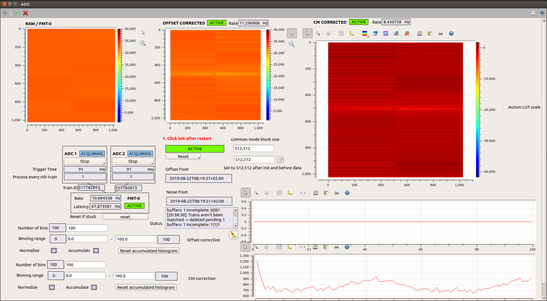
Fig. 8.12 The calibrated preview and online histograms (see Histograms). This is based on an old scene, which is turned into a new scene shown in Fig. 6.4.
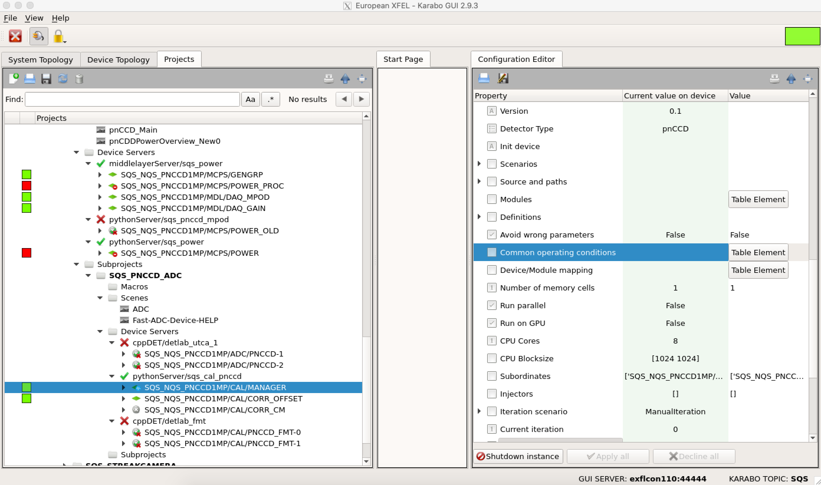
Fig. 8.13 Change the Table Element properties of the Common operating conditions field on the SQS_NQS_PNCCD1MP/CAL/MANAGER Karabo device before loading the new dark constants. Otherwise, the dark constants will be loaded from those dark runs with whatever properties that are saved in the Table Element of the Common operating conditions field of the SQS_NQS_PNCCD1MP/CAL/MANAGER Karabo device. The same table is found on the pnCCD_Acquisition scene.

Fig. 8.14 Change the operating conditions before loading new dark constants. Temperature is in degK.
8.10.3. Preview Histograms
There are two online histograms in the pnCCD_Acquisition scene: both are based on calibrated preview images described above. In the first one, only the offset correction is applied, while the second one has the common mode correction in addition to the offset correction. You may need to play with the number of bins and bin range from and to parameters corresponding to each histogram to have the desired view.
One can also guide the SQS scientists on shift as to whether or not they are operating in single photon zone, where each detector’s pixel is only hit by one photon at the time. In this case, you will see two peaks on the online histograms: one has a centroid of zero (due to offset correction, this is the noise peak) and the other peak should represent the scattered beam detected by the camera. Its location should be somewhere other than zero ADU (see Table 8.2). Therefore, if there are more peaks on the histograms, this means the detector pixels are being hit with more than one photon at the time.
In addition, one can determine whether or not the image is being saturated. If the beam intensity is too high or if the beam is hitting the camera (which has a serious damaging effect to the detector), the peaks on the online histograms will show saturation representing a clipped signal on the oscilloscope.
One can also use the offset corrected histogram to determine whether or not the offset correction is accurately obtained for a particular gain setting. If so, the noise peak should be centered at zero ADU.
8.11. Pixel Saturation Levels
The FastADC digitizers have 16-bit resolution. Therefore, the electronics reach saturation at \(2^{16} = 65536\) ADU. However, due to a limited Full Well Capacity (FWC), the pnCCD detector may reach saturation at ADU values far less than the electronics saturation level. The FWC depends on the HV bias value applied to the two sensors and the pnCCD gain. Since each operation mode has different bias voltage, in principle the FWC is not the same for all operation modes. But, it is safe to say that the pnCCD detector reaches saturation at around 30000 to 40000 ADU. Therefore, if the experiment requires high FEL intensities, make sure that the corrected images (see CalibratedPreview) do not go over this limit; otherwise, the data will be affected by pixel saturation. Ask the SQS members to reduce beam intensity if the detector is being saturated.
8.12. Long Shutdown Periods
If pnCCD is not going to be used for an extended period of time:
- Stop the sequencer (see
SequencerCTRL). - Stop the acqusition of the FastADC digitizers (see
ADCs). - Power down the pnCCD (see
PowerOFF). - Turn both chillers OFF (see
Chillers). - Set the temperatures of the pnCCD top and bottom modules’ setpoints to above \(+15\) degC.
- Ensure the temperatures of the pnCCD top and bottom modules have reached above \(+15\) degC and have stabilized.
- Ensure that both Boralectric heaters are OFF. Set the
Rangefields of both heaters to zero on thepnCCD_Mainscene only after the detector is warmed up. - Ensure both heaters for the cold heads are OFF. Also, turn OFF the power supply for those latter heaters (see
ColdHeadHeaters). - Ensure MPOD system and the interlock system and all other power supplies and other electronics of the pnCCD (including the Lake Shore unit) are OFF.
- Make sure the vacuum system is safely secured for a long term shutdown (see
VacuumShutdown). - Make sure if pnCCD chamber is going to be moved out of the SQS beamline, it is stored in a clean area to avoid dust contamination in the chamber.
- Make sure the pnCCD electronics rack is secured safely somewhere clean.
- Secure all cables (in particular the Fiber Optic cable) and make sure they are safe to prevent damage to the cables.
8.12.1. Safe Mode for Vacuum System
This is reached when:
- SQS beam shutter in the tunnel is closed.
- Gate valves \(V_{1}\), \(V_{2}\) and \(V_{3}\) (see Fig. 5.22, Fig. 5.18, and Fig. 5.22) are all closed.
- The turbo pumps \(TP_{1}\) and \(TP_{2}\) (see Fig. 5.18) are stopped and turned OFF.
- The emergency power OFF procedure is successfully executed (ask SQS members).
- All power supplies for motion system of the pnCCD, motors and encoders are OFF.
- Turn OFF the Maxigauge.
- Disconnect all cables and make sure they are secured and safe.
Footnotes
| [1] | Looking at the pnCCDPowerOverview_New0 scene, locate phi_amp boxes (there are two, one for the top and one for the bottom pnCCD sensors). if you multiply the measured voltage (the value in V) by the measured current (the value in A) per each pnCCD module, you will obtain the power output from that module. The sum of both power outputs is the total power (in Watts) that the pnCCD detector outputs. |