Interlock
Interlock logic should not be reconfigured from the Karabo layer.
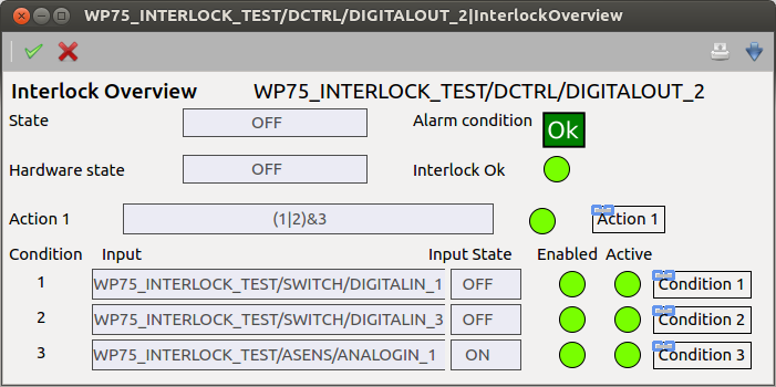
However it the logic is decoded and visible using the automatically generated scenes,
all accessible from InterlockOverview

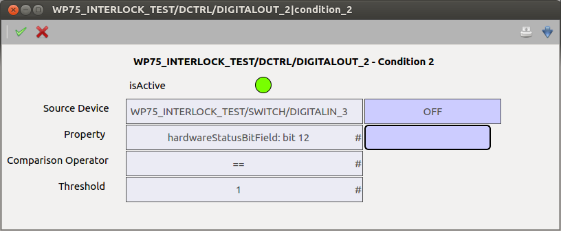
The decoded description of the interlock condition is available in each condition scene

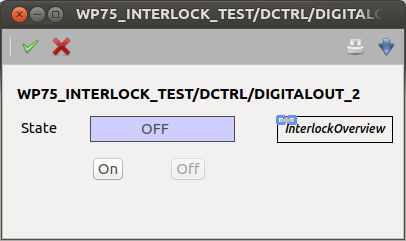
In devices with a deafult scene (i.e. analog and digital IO, motors, valve, and pumps), a device scene link is added dynamically depending on the configuration in the default scene.

Detailed description of the interlock properties
Here is the structure that describes the interlock per device.
AConditionStateis a 32bit bitmask. Each bit is set when the relative condition is true. Each single bit is translated as a boolean property and is visible in the condition node under the name isActive. This variable will be pushed to the TCP layer at each update.
AActionStateis a 32bit bitmask. Each bit is set when the action describe by the respective AActCommand is active. Each single bit is translated as a boolean property and is visible in the action node under the name isActive. This variable will be pushed to the TCP layer at each update.
ACndEnable_[1-32]is a Boolean that is true when the respective condition is enabled It is accessible in the interlock.condition[N] node.
ACndValue1_[1-32]the type of this plc attribute depends on the source type and is a copy of the source value.
ACndSource1_[1-32]Is a String and defines the DeviceId of the source.
ACndSrc1Detail_[1-32]is a 32 bit unsigned integer. It defines the PLC property to be examined by the interlock system from the source. It is the index number of an enumerator at the pathxfelPlcFramework/DUTs/ST_SourceDetail.TcDUTin the PLC framework repository.
ACndValue2_[1-32]the type of this plc attribute depends on the source type and is a copy of the optional second source value (e.g. comparison between 2 PLC properties).
ACndSource2_[1-32]Is a String and defines the DeviceId of the optional second source value (e.g. comparison between 2 PLC properties).
ACndSrc2Detail_[1-32]is a 32 bit unsigned integer. It defines the PLC property to be examined by the interlock system from the source. It is the index number of an enumerator at the pathxfelPlcFramework/DUTs/ST_SourceDetail.TcDUTin the PLC framework repository, e.g. 2 means status bit number 2.
ACndAriOP_[1-32]is a 32 bit unsigned integer. It defines the operation to be performed between source1 and source2 in the calculation of the condition. It is the index number of an enumerator at the pathxfelPlcFramework/DUTs/ST_AriOp.TcDUTin the PLC framework repository, e.g. 2 means subtraction.
ACndComOp_[1-32]is a 32 bit unsigned integer. It defines the comparison operator to be used to evaluate the interlock condition. It is the index number of an enumerator at the pathxfelPlcFramework/DUTs/ST_ComOp.TcDUTin the PLC framework repository, e.g. 2 means status greater or equal.
ACndThreshold_[1-32]the type depends on the input type. It is the constant against which the expression will be compared to.
ACndFilterTime_[1-32]is an 32 bit unsigned integer. It is the number of milliseconds the condition ought to be true before triggering an action.
ACndHisteresis_[1-32]the type is detail-dependent and it defines the histeresis band for the condition to be cleared. It is invalid for booleans.
AActCommand_[1-32]is a PLC PAIR. it is a vector of Uint32 words that is coded like a Pair from Karabo to the PLC (PLCID,KeyId,nValues,[Values])
AActLogicStr_[1-32]is a string and describes the logic of the respective action.