Bunch Arrival-time Monitors
BAM System Functionality
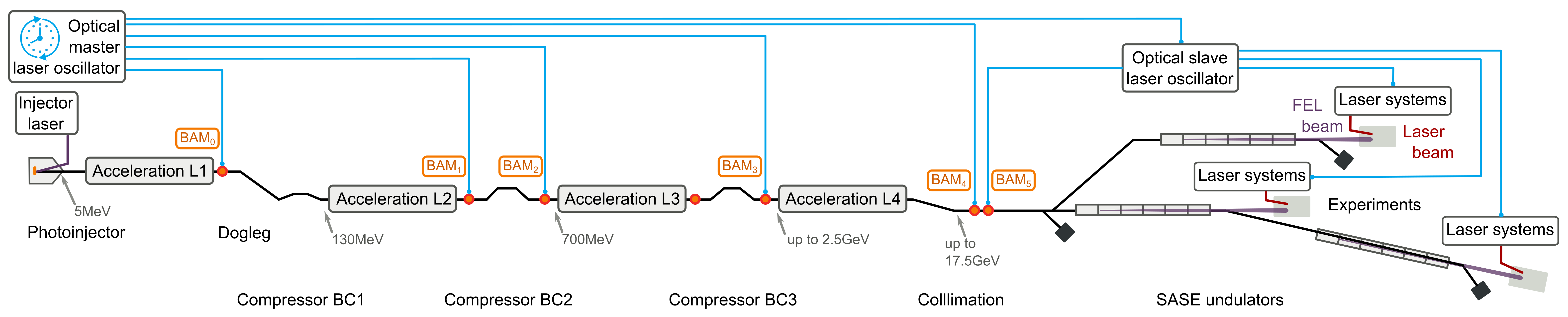
The Bunch Arrival-time Monitor (BAM) uses a relative measurement method which compares the timing of each electron bunch against a laser pulse provided by the optical reference system (LbSync); to the same time reference, the pump-probe lasers are phase-locked.
The unit of the BAM data are picoseconds. The x-axis is given in microseconds, showing the bunch filling pattern as defined in the main timing system.
BAM Locations at XFEL
| Machine operation | SASE 1 | SASE 2 | SASE 3 |
| 47.I1 | 414.B2 1932M.TL 1932S.TL |
414.B2 1932M.TL 1932S.TL |
414.B2 1932M.TL 1932S.TL |
| 181.B1 | |||
| 203.B1 | |||
| 392.B2 | |||
| 414.B2 | |||
| 1932M.TL | |||
| 1932S.TL |
Description of Data Sources
The original DOOCS property of the BAM data has an array length of 7222 entries, and is filled in a 9 MHz pattern
The length of 7222 is derived from an underlying 9 MHz bunch pattern with 800 μs macro-pulse at FLASH: (800 * 1.3 / 144) * 1000 = 7222 entries. While for XFEL this number should be ( 600 * 1.3 / 144 ) * 1000 = 5416 entries. However, a special decision was made to keep 7222 entries during the process of server development in agreement with the software experts at MSK and MCS since they have to deliver a data structure that accommodates the needs of different user groups.
Mapping the recorded BAM to different SASEs
TODO:
Properties
Spectra
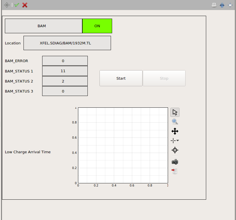
LOW_CHARGE_ARRIVAL_TIME
Calibrated arrival time data from the “low-charge channel”: - calibrated arrival time for all bunches and all sub-macropulses - full length = 7222 entries in 9 MHz pattern - x-axis: picoseconds
Integer Values
For converting to binary word with 12 bits to display status bits/logic plot.
BAM_STATUS.1
- Submacropulse 1 (RF Flattop 1) general status of the BAM Channel
- bit 0 = data is valid,
- bit 1 = at least 1 bunch is requested/allowed from main timing,,
- bit 2 = calibration is on,
- bit 3 = internal feedback is on,
- bit 4 = tuning mode is on
BAM_STATUS.2
- Submacropulse 2 (RF Flattop 2) general status of the BAM Channel
- bit 0 = data is valid,
- bit 1 = at least 1 bunch is requested/allowed from main timing,,
- bit 2 = calibration is on,
- bit 3 = internal feedback is on,
- bit 4 = tuning mode is on
BAM_STATUS.3
- Submacropulse 3 (RF Flattop 3) general status of the BAM Channel
- bit 0 = data is valid,
- bit 1 = at least 1 bunch is requested/allowed from main timing,
- bit 2 = calibration is on,
- bit 3 = internal feedback is on,
- bit 4 = tuning mode is on
BAM_ERROR
- General error code of the BAM System:
- bit 0 = no error
- bit 1 = error from front-end,
- bit 2 = link not locked,
- bit 3 = MLO not locked,
- bit 4 = error from Motor.1 (for Submacropulse 1),
- bit 5 = error from Motor.2 (for Submacropulse 2),
- bit 6 = error from Motor.3 (for Submacropulse 3),
- bit 7 = error from Motor T (for time-delay between “low-charge channel” and “high-charge channel”),
- bit 8 = toroid connection time-out,
- bit 9 = link connection time-out,
- bit 10 = MLO connection time-out
Detailed documentation:
https://confluence.desy.de/display/SDiagPublic/BAM+Data+Structure