Monochromator and Undulator Energy Introduction
Purpose of this middlelayer device is to enable photon energy scans from the scantool, with the photon energy provided as setpoint for both the monochromator(s) and the undulator(s). While the monochromators will move for every scan step, the undulators will move only when the requested energy is outside of the emitted spectrum. The calibration is described here below.
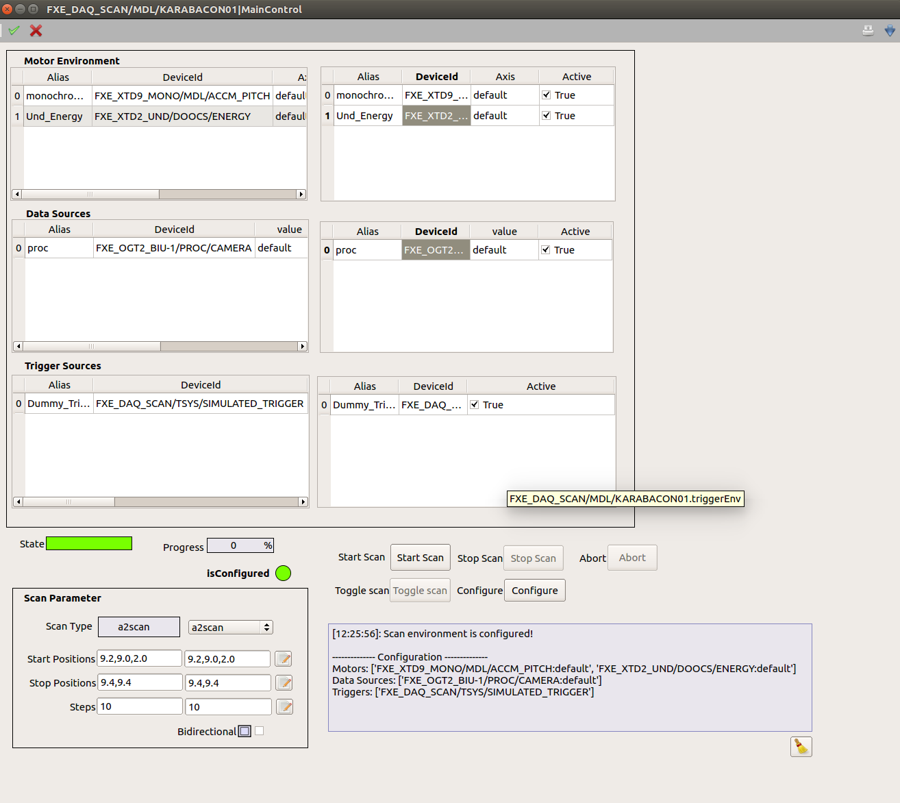
In the scantool, the “motors” “/FXE_XTD9_MONO/MDL/ACCM_PITCH” and/or “FXE_XTD2_UND/DOOCS/ENERGY” have to be included, depending on which device has to be scanned. For the mono this is the “top-level” MDL, which forwards the target energy to the “low-level” monochromator MDL devices “FXE_XTD9_MONO-[1,2]/MDL/ACCM_PITCH”, which contain the calibration photon energy -> motor position. Calibration of the undulator is done directly in “FXE_XTD2_UND/DOOCS/ENERGY”. The scan is performed as “ascan” or “a2scan” depending if only mono or undulator is moved or both.
Monochromator Calibration
If a discrepancy is observed between the monochromator actual energy and the physically transmitted photon energy (observed e.g. from an edge scan), most likely the linear stage offset \({x_0}\) must be adjusted. This is done by using the “calibrate” function available on the two “low-level” monochromator devices “FXE_XTD9_MONO-[1,2]/MDL/ACCM_PITCH”. Move the monochromator to where it transmits the desired energy (e.g. the edge position), type in “Calibrated Energy” and click “Calibrate”. This has to be done for both mono devices individually. If only one monochromator is to be scanned, go to “/FXE_XTD9_MONO/MDL/ACCM_PITCH” and set the “Motor Environment” accordingly.
Undulator Calibration
Also the undulator calibration should be checked from time to time. After the monochromator is calibrated, scan I0 against the undulator energy and move them to the maximum. Then go to the undulator device “FXE_XTD2_UND/DOOCS/ENERGY”, type in the “Calibrated Energy” and click “Calibrate”. It will simply derive a scaling factor between the undulator setpoint \({E_{set}}\) and the emitted energy \({E_{emit}}\), which is called “Calibration Factor” in the device. It is defined as \(\alpha = \frac{E_{set}}{E_{emit}}\). The undulator will execute a move only if the set energy \({E_{set}}\) is outside of the range defined by the tolerance \({t}\) according to \({E_{range} = E_{set} \cdot \left(1 \pm \frac{1}{100}\right)}\). As an example, the tolerance is typically \({t = 0.05}\), and for an energy of \({9\ keV}\) this results in a range of \({\pm 3\ eV}\) in which it is not necessary to move the ondulators.
Monochromator Geometry
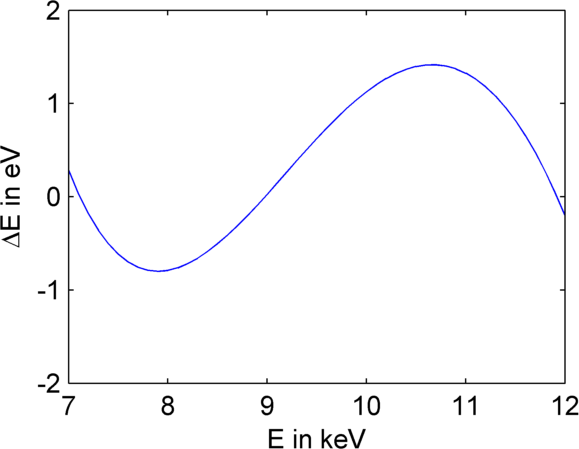
Two different models can be used to mathematically describe the motion of the monochromator with different accuracy. The discrepancy of the simplified model as compared to the exact model is less than \({1\ eV}\), if calibrated correctly over the entire scan range, as shown in Fig. 1. The simplified model has four parameters and therefore it needs four data points of scanned absorption edges at energies \({E_i}\) at corresponding motor positions \({x_i}\) for an accurate calibration. The exact model needs six such data points.

Fig. 1 <fig-models>: Energy difference between the two mentioned
geometry models after fitting three reference energies at \({11.919\ keV}\) (Au L3),
\({8.979\ keV}\) (Cu K) and \({7.112\ keV}\) (Fe K).
Due to the mentioned good precision of the simplified geometrical model, it was initially developed only a Karabo device implementing such model. In the remaining section this model and device will be described.
Simplified Geometrical Model
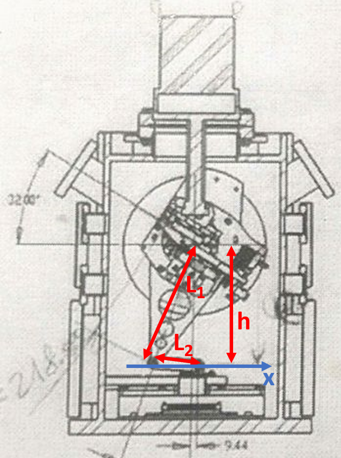
The geometry of the monochromator is presented in Fig. 2.

Fig. 2 Fig. 2: Geometry of the monochromator.
The main simplification in this model is that the angle \({\theta}\) is assumed to be determined directly by the linear stage (not via an extra joint in between).
The parameters to be configured via Karabo by the instrument scientist are:
- Proportionality constant: Distance \({L_1}\) between the linear translation axis and center of rotation of long arm. The default value is set to 213, without minimum and maximum limits;
- Bragg Constant: Conversion parameter \({d_B}\). In case of Si111 material at ambient conditions it is
- Angular Offset: \({\theta_0}\). It has default value 0.0, and minimum and maximum limits set to -1 rad and +1 rad, respectively.
Mapping between motor position and target energy can be formulated by below equation:
Where, \({E_t}\) is the target photon energy; \({x_t}\) is the target Stage/motor position; \({x_0}\) is the translation stage offset
To use the above model, first we need to perform the calibration. Calibration can be done by setting the calibrated target energy(E_c) to calibrate target parameter in karabo device and then by executing the calibrate slot from the karbo device. The calibration function reads the current motor position x_c and compute the offset x_0 using the below formula
Where, \({E_c}\) is the calibrated target energy \({x_c}\) is the current motor position
To calculate the actual energy from the current motor position, the MDL device applies the inverse operation,

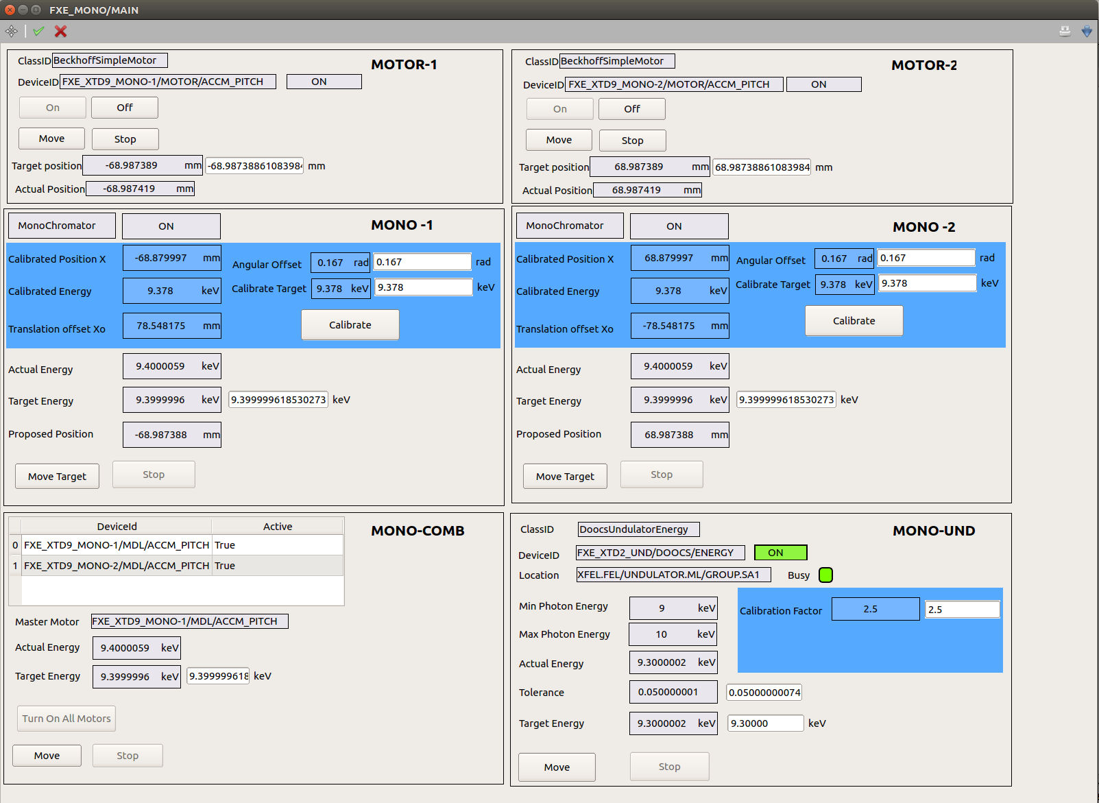
Fig. 3 Fig. 3: A scene allows to monitor and configure the Energy scan devices (Monochromator(s) and Undulator device from a dedicated GUI.

Fig. 4 Fig. 4: Integration into scan tool