Introduction
The pplVacuumControl device is designed to provide an automatic control of the vacuum in the beam section of the pulse probe laser [1] (located where the beam is delivered to the instruments).
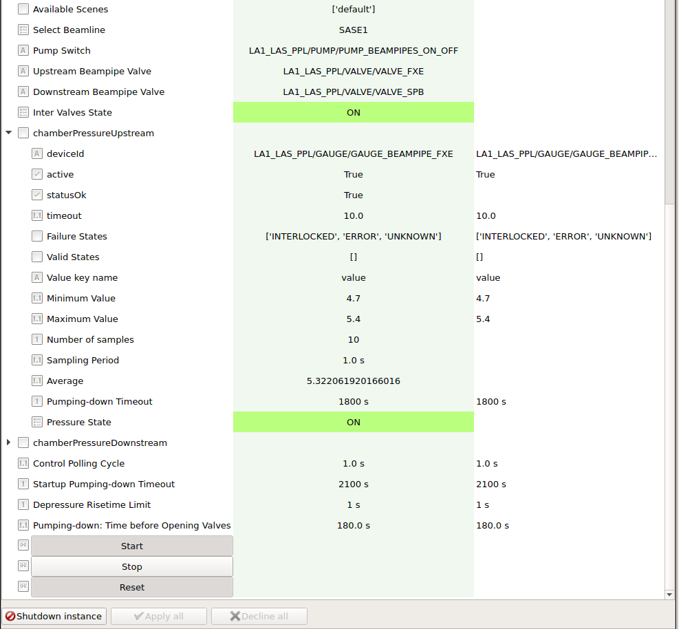
The configuration editor of the device is shown in Fig. 1.
The operational principle is graphically displayed in Fig. 2, considering as an example the beamline in the laser hutch in SASE1. Identical considerations can be done for the laser beamline in SASE3; for SASE2 only one beamline exists, but similar working principles can be applied.
From the hutch two individual beamlines provide the pulse probe laser separately to the two SASE instruments. In this example FXE and SPB, located on left and right side of the beamline sketch, respectively, are considered. In each instrument section a dedicated gauge (controlled by the Beckhoff PLC) continuously measures the pressure. The gauge readout is presented in arbitrary units as a running average of N continuous measurements. The parameter Number of samples defines how many continuous measurements are considered in the running average. The measurements are taken at Sampling Period intervals.
The minimum and maximum values (Maximum Value and Maximum Value in the device editor) are provided by the PPL group.
Note that the change of pressure value is acknowledged only if the difference with respect to the previously reported value is larger than the so called Epsilon parameter; this parameter can be configured in the configuration editor of the corresponding karabo gauge device.
The control of vacuum is activated (deactivated) by clicking the Start (Stop) button. If the control is activated, as soon as the pressure overshoots the maximum limit, the pump in the pre-chamber (located in-between the valves in the two sections) is started to create a pre-vacuum in front of the relevant valve. The state of the pipe in-between the two valves is ON in case both valves are closed; it is OFF otherwise.
After an user-configurable interval (Pumping-down: Time) the valve in the section is opened and the pressure decreases. In case both sections have the pressure above the limit, priority is given to the section which has the lowest Pumping-down Timeout value. This value is the maximum interval allowed to bring the pressure below the limit.
When the gauge readout in the section under pumping gets lower than the minimum limit, the valve is closed and the pumping stopped.
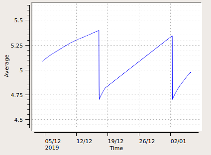
An example of the change of the section pressure when controlled by the karabo device is presented in Fig. 3.
In the configuration editor of the device, the settings of some parameters can be done with the device in control mode active, as for the lower/upper limits of the pressure. In contrast, some parameters should be configured before instantiating the device; this applies for example to the pump, valves and gauges to be used.
During pumping, in case the pressure remains above the maximum after the timeout Pumping-down Timeout, an error is issued, warning of a possible leak or of a possible malfunctioning of the pump. A leak may also be present, if pumping is needed more frequent than the Depressure Risetime Limit. Also in this case the device enters an error state. As typical to many karabo devices, the error state can be removed using the button reset. If the error situation persists, the alarm will be again issued. The parameters Pumping-down Timeout and Depressure Risetime Limit should be tuned by PPL operators according to the type of pumps and pipes used in the system.
| [1] | M. Pergament et al., “Versatile optical laser system for experiments at the European X-ray free-electron laser facility,” Opt. Express 24, 29349-29359 (2016) |


