General Information
Daily operation
The Karabo scene called PP_LASER_OVERVIEW in the project SCS_ILH_LAS gathers all important controls of the PP laser for a normal useage, i.e. when the beam is aligned in ILH and/or during user operation. The scene looks like this:
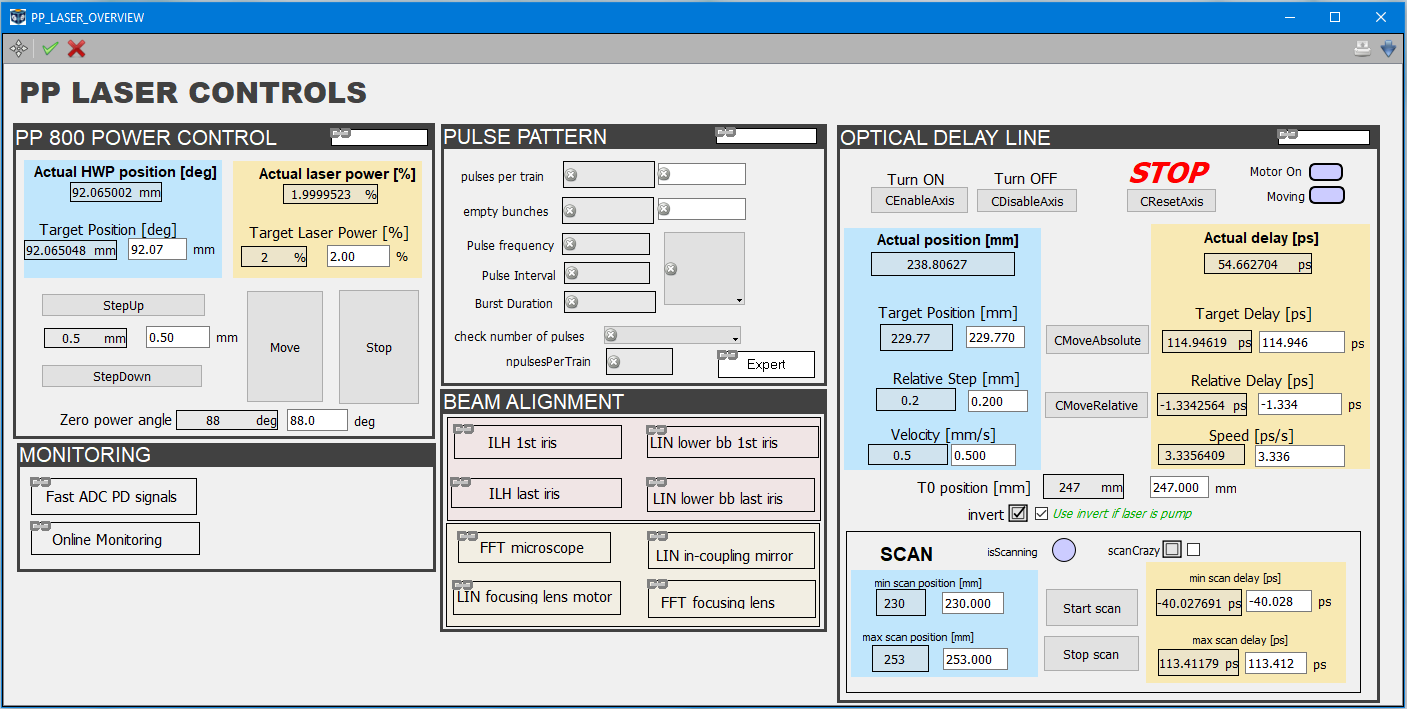
Each section is made as simple as possible, providing only the essential controls. Links to more advanced features are provided in the upper right corner of each section (white rectangles).
Power control
The section PP 800 POWER CONTROL allows changing the pulse energy of the laser by rotating a half wave-plate (HWP) located in front of two thin film polarizers (TFP). The polarization is rotated by the HWP and only the S component (vertical) is reflected by the TFP pair. The resulting energy is a function of the angle of the HWP:
with \(\theta_0\) the angle for which the beam is fully attenuated.
For a given power percentage p, the corresponding HWP angle is given by:
Usually, \(\theta_0\) is set and does not change, but it could be necessary to change it by updating the field “Zero power angle” at the bottom of the section.
Monitoring
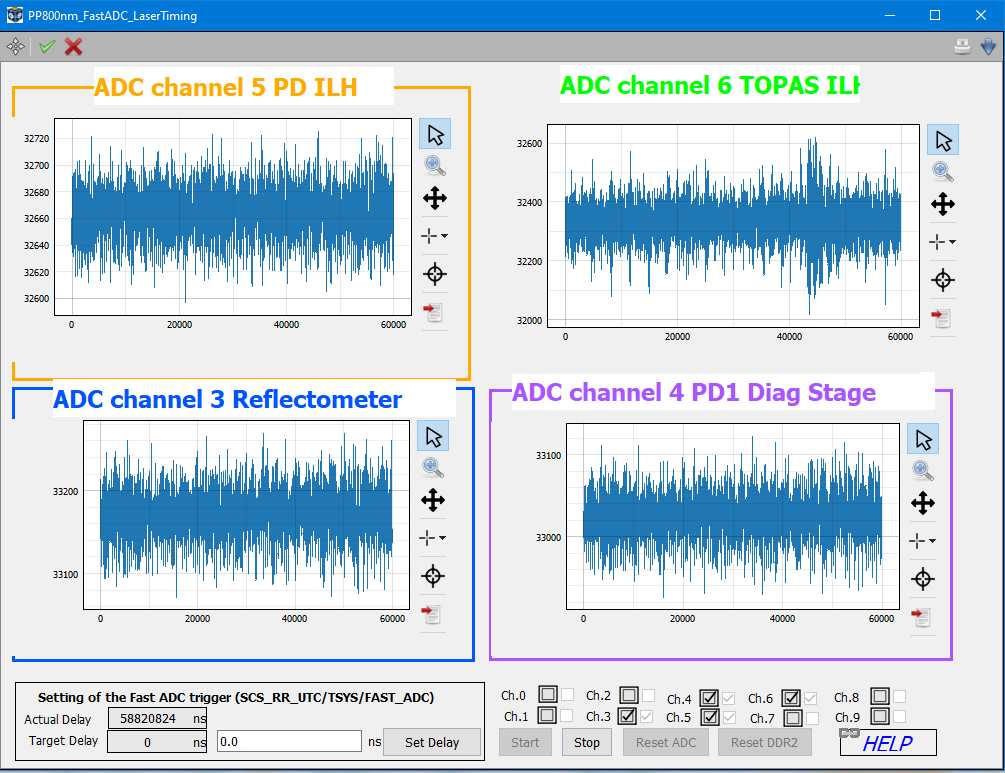
The section MONITORING provides links to scenes that help vizualize the situation. The scene Fast ADC PD signals shows the time traces of various photodiodes (PD) that are connected to different channels of the Fast ADC digitizer.
- The PD on Channel 5 is located after the second mirror in the ILH.
- The PD on Channel 6 is located after the first thin film polarizer at the output of the TOPAS.
- The PD on Channel 3 is the one on the reflectometer of the FFT.
- The PD on Channel 4 is located on the diagnostics stage of the FFT.
Note
It is good practice to keep this scene open, to quickly check if the laser pulse is present in ILH and/or Exp Hutch.
Pulse Pattern
The section PULSE PATTERN enables to select or create a simple, regular laser pulse pattern. This pulse pattern is based on a grid of 4.5 MHz. Once we have entered the number of pulses and the number of empty bunches between two pulses (this, in turn, defines the repetition rate), we can press the button sendToDOOCS to activate our pattern. We can usually monitor the changes by looking at the PD signal in ILH.
The number of pulses can be check by pressing the button AUTOFIND. It is the exact same button as the one used by the Timing Monitor (see …link…).
For more advanced patterns, see here.
Optical delay line
The main optical delay line is located in the ILH. It consists of two 3 inches mirrors at 45 degrees on a 500 mm long Feinmess stage with absolute encoders. The Karabo device that controls the stage is SCS_ILH_LAS/MOTOR/LT3.
Note
Increasing values of the motor position correspond to an increasing path length.
The stage must first be turned ON before any movement. After its use, it should be turned OFF.
A macro positionToDelay_LT3 is used to convert position in mm into time delay in ps. The delay is arbitrary, and the origin can be fixed with the field T0 position [mm]. Each position field (Target position, Actual position, Velocity…) has its time delay counterpart (Target delay, Actual delay, speed…).
Note
The sign of the time delay is arbitrary. Usually, a positive delay corresponds to the probe beam coming later than the pump beam. When using the laser as pump, the check box invert can be checked to comply with this convention.
It is possible to scan the delay stage by using the subsection SCAN. The stage will continuously oscillate between the min and max scan values (position or delay).
The scanCrazy option uses a Beta distribution of target positions within the range specified. This should avoid, in principle, the accumulation of points at the edges of the scan range due to the slowing down of the motor.
Warning
The scan macro can be unreliable. If it does not behave as expected, stop the motor, move to a position inside of the scanning range and try again. The situation should improve when the macro is turned into a MDL.
Contacts
| Name | Phone number |
|---|---|
| OCD 1 | 0170 8763242 |
| OCD 2 | 0151 46471885 |
| las-op@xfel.eu | |
| Guido | 6976 |
| Tomasz | 6779 |
| Florent | 6447 |
| Dimitros | 6940 |
| Hutch | 86467 / 86477 |
| Riccardo | 6407 |
Current Setup and Layout
The current laser setup is documented on google drive:
scs.main > scs.instrument > Instrument_Laser_Hutch > Beam_path
Switch between paths
Warning
Careful: Do not use this functionality from the control room. You need to be present in the ILH and make sure the main shutter into the ILH is closed!! Otherwise the beam points in an undefined direction.
We automatized the mirror movements to switch between the setups. In the project ILH you find a scene PP800nm_Topas_Switch that does everything.
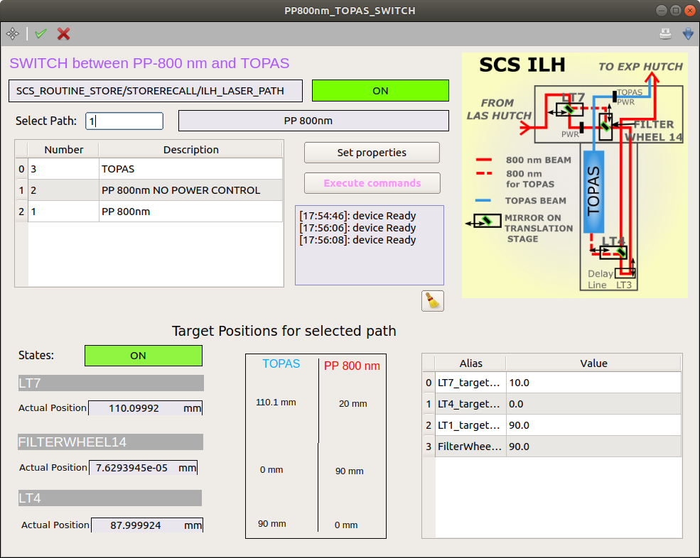
- Select the path you wish to use. Make sure the stages are not physically blocked by anything.
- Press set properties. This sets the corresponding target values.
- Press excecute commands. The stages move to their target position.
Beam aligment into ILH
- The PP laser runs continuously and there are usually no big drifts after a few hours of operation. Nevertheless one should check whether the pointing into the ILH changed. (update)
- After this one can check the last iris in the ILH. The mirror motor needed to adjust the beam position on this iris is integrated into the scene. In case the beam pointing into the ILH has been adjusted, only small or no adjustments on the last one should be necessary.
- You can also check the pointing through the pipe to the LIN. For this one needs to go into the experimental hutch, put it in class 4 mode, and close the first iris after the pipe. One can then use the corresponding scene to properly align the beam through the pipe (LIN lower bb 1st iris).
PPL pulse pattern operation
Riccardo from Controls developed the PPL pattern selection tools. They can be found in the xfel read_the_docs.
The PPL oscillator runs at 54.166667 MHz a factor 12 faster than the 4.5MHz base repetition rate of the accelerator. The amplifier runs at a maxium repetition rate of 112.8 kHz, another factor of 40 slower than the 4.5MHz. This repetition rate relates to:
- 4.5 MHz base => 1 OL pulse out of 40
- 2.25 MHz base => 1 OL pulse out of 20
- 1.128 MHz base => 1 OL pulse out of 10
Beam characterization
Automatized power control in ILH.
Careful: There is no laser safety installed around the LTS. When moving the beam might point in an undefined direction. Make sure not to use this when people are working in the ILH.
(to be documented)
Beam stabilization
Full documentation:
https://git.xfel.eu/gitlab/karaboDevices/beampositioncontroller
Eventually, it will be accessible through the karabo-gui directly.