Introduction
The TemBeamLock device is designed to provide a compensation to PPL [1] beam pointing instabilities, such as drift of steering mirrors, air turbulence, and thermal effects of the optical elements. This feedback loop is obtained here using the Aligna system by TEM Messtechnik [2]. Hereafter the Aligna device will be referred to as TEM.
The TEM is capable to maintain the beam axis stable over relatively fast time-scales in the area where its actuators (mirrors) and position detectors (cameras) are located.
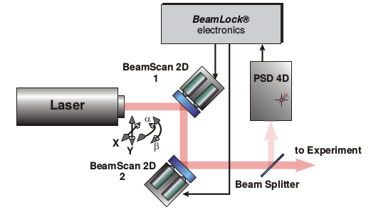
The principle of operation of the feedback loop is described in the following. A sample of the beam is sent to a position sensitive detector which calculates the laser beam position and its angle. The detector is typically made of two cameras. The measured deviation signals of the laser axis with respect to the reference axis are processed continuously by the TEM electronics. Control signals for four piezo actuators of two mirrors (twice per mirror) are generated to keep in a closed loop keep the laser beam exactly at the reference axis. A diagram of the TEM configuration is presented in Fig. 1.

Fig. 1 The picture describes the principle of operation of the TEM device for the beam stabilization.
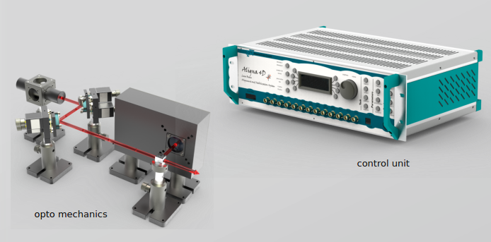
An example of the hardware components located in the beam line is shown in Fig. 2, along with the control unit of the system. At XFEL, the controller is connected to the control network via a Lantronix UDS1100 RS232-to-USB interface [3].
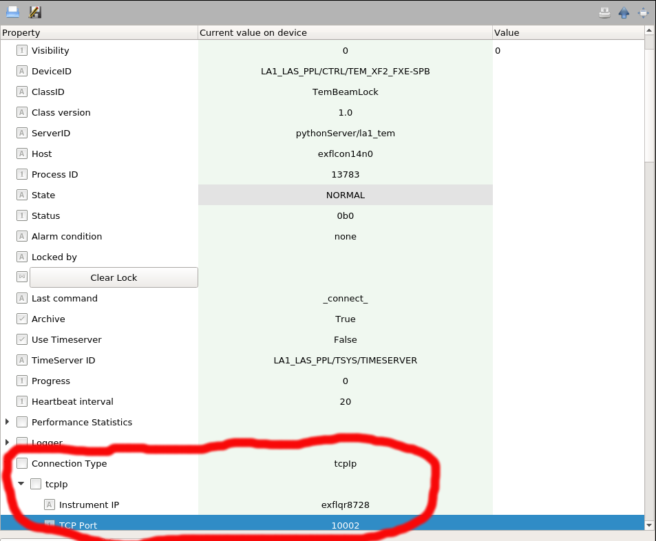
The connection to the Lantronix interface is done configuring the mandatory parameters “Instrument IP” and “TCP Port” in the configuration editor of the karabo device, Fig. 3,

Fig. 3 The connection of the Lantronix interface to the TEM is done via mandatory parameters in the Configuration Editor of the TemBeamLock device.
The network address of the Lantronix device can be provided as IP number, as well as karabo network alias, as shown in :numref:`Fig. %s <fig-editor-tcp>. The Lantronix interface can be connected independently to two different serial devices, using either the port 10001 or 10002. By choosing a port number, the TemBeamLock device connects to the Lantronix, and send (receive) information to (from) the serial device connected to that port. The configuration of the interface to correctly communicate with the attached device is presented in the :ref:`troubleshooting section <TemBeamLock:troubleshooting>.
Selecting the reference position coordinates for the beam impinging on the two cameras. The TEM will steer the beam (via the actuators) such that it will eventually impinge on the two cameras in the reference position coordinates and within the accuracy set by the user. These reference positions are hereafter referred to as setpoints.
Via calibration, a linear correlation is extracted between the position set in one sensor (\(S_x\), \(S_y\)) of the TEM (its setpoint) and beam position measured in the camera (\(B_x\), \(B_y\)), determined using Gaussian fits of the profiles along the x- and y-axis,
Using this correlation one can shift the beam position at the camera location by accordingly changing the setpoint in the TEM, e.g.,
Thus, in case a beam drift \(\Delta B_x = B^{'}_x - B^0_x\) was observed, to bring the beam back to the desired position in the camera the shift \(\overline{\Delta B_x} = - \Delta B_x\) should be induced. This is achieved using the calibration linear function, above mentioned,
changing the TEM setpoint to the new value
The temSlowDriftCompensator device will thus change the TEM setpoints \(S_x\) and \(S_y\) in order to keep the beam at the reference coordinates (\(B_x\) and \(B_y\), respectively) on the camera.
The drift compensation loop parameters are configurable. Its functioning can be monitored through the Karabo device, Fig. 4,
The Karabo ID of the image processor device (analyzing the data from the camera external to the TEM) should be provided before instantiation in the “Image processor” parameter, as well as the name of the karabo TEM device (“TEM device”). The TEM device is a device of class TemBeamLock which communicates with the actual TEM hardware via one of the two channels of the the Lantronix interface. The channel to be used (“TEM channel”) is also mandatory.
The desired value for the beam coordinates in the camera should be set in the parameters “Target center X/Y”. The actual beam position and displacement from the reference coordinates are displayed by the parameters “X/Y coordinate mean value and X/Y Pixel Shift”, respectively. The beam position is presented as the average over N measurements, where N is set by “Desired width of average window for center coordinates”. The maximum allowed displacement with respect to the reference coordinates should be set in “Maximum COM displacement” (here COM stands for center of mass of the beam profiles measured along the camera x- and y-axis). In case the beam displacement exceeds this value the device state will go to error. The parameter “Timeout for Image processor” is the time to wait before going into error when the image processor is not updating its values.
By clicking the button Calibrate, the calibration procedure is performed and a functional relation between the beam position values in the camera and the setpoint values in the TEM is extracted (for both the x-axis and y-axis) via a linear fit. The slope parameters extracted in the calibration are shown in the variables “Ax Coefficient” and “Ay Coefficient”. In case those values were known from a previous calibration the user could type them directly in the editor. Saving them before instantiation (thus storing them in the project database) will allow to use them as default values for the device. If a new calibration is performed (due to possibly a change in the environmental or setup conditions), the previous calibration values are saved (for safety reasons) in the variables “Previous Ax/Ay Coeff”. The calibration is done measuring the beam position during the scan of the setpoints. The scan start and end points are taken simmetrically with respect to the current setpoint. The number of steps and the step size can be set in the parameters “TEM calibration steps number” and “TEM calibration step”.
The automated drift correction is enabled (disabled) by clicking Start (Stop). When the monitoring is active, as soon as the beam position displacement is larger than the value set in “Target Accuracy” the device will send to the TEM a new setpoint value in order to bring closer to the reference position. In case the proposed setpoint exceeds the maximum allowed value of the setpoints (“Maximum TEM drift”) the device state will go to error. The control loop can be slowed down for safety (e.g., to prevent oscillations or overshooting) by setting “X/Y coefficient weight” to a value lower than unity (this acts as damping for the feedback loop). The time to wait before reading beam center coordinates after changing the TEM setpoint can be set in the variable “beam Image settlement time”. The interval between two subsequent checks of the beam mean position is also set by this value.
An example of beam stability taken when correcting for the drift the ppl beam for the SPB instrument is presented in Fig. 5,
In case the current position of the beam should be considered as the reference position, the user should use the button “Set target position”.
When the TEM device is not regulating, wait for the time interval “maximum time TEM not regulating” before going into error state. This parameter should be tuned when dealing with temporary HW failures.
| [1] | M. Pergament et al., “Versatile optical laser system for experiments at the European X-ray free-electron laser facility,” Opt. Express 24, 29349-29359 (2016) |
| [2] | Automated Laser Beam Alignment and Stabilization System (Aligna), TEM Messtechnik, http://www.tem-messtechnik.de/EN/aligna.htm |
| [3] | Lantronix External Device Server UDS2100, https://www.lantronix.com/products/uds2100/ |


