ePix100 Overview
This documentation is meant to provide a general overview of the ePix100 detector, covering its functionality and operation, serving as a resource for detector support.
The ePix100 detector [1] is a backside illuminated charge-integrating hybrid pixel detector with single photon resolution capability and a dynamic range of up to ~100 8keV photons (without dynamic gain switching). It belongs to the family of ePix detectors developed at SLAC National Accelerator Laboratory.

Presently, there are two operational modules which are regularly used at MID. Two other modules have previously been used at HED but are currently non-operational. Therefore, parts of this documentation (such as karabo device names) are focused on the ePix100 detectors of MID.
Specifications
The main specifications of the ePix100 detector are listed below:
| Parameter | Value |
|---|---|
| Sensor | 500 μm Si |
| Pixel size | 50×50 μm² |
| Pixel distribution | 384×352 (×4 ASICs) |
| Active Area | 38×35 mm² |
| Noise (ENC) | ≤ 50 e⁻ |
| Dynamic Range | 100 photons (8 keV) |
| Max Frame Rate | 120 Hz |
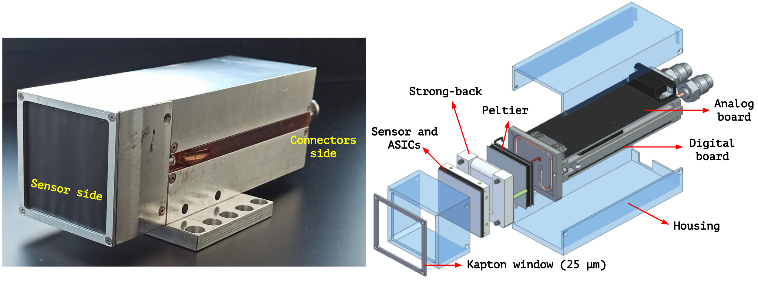
The detector consists of 3 main components:
- Camera head: A 500 μm silicon sensor bump-bonded to 4 ASICS (2x2), making for ~0.5 Megapixels. Each ASIC is divided into 4 banks (super-columns) of 96 columns which are multiplexed into a single analog signal, each is then digitized by a single ADC channel.
- Analog board: Containing two 16-channel, 14-bit ADCs to digitize the analog signals from the ASICS as well as other critical signals. The analog board is also responsible for receiving and distributing power supply for the PCB boards and ASICS, bias to the sensor, trigger and the signal from the thermoelectric controller (TEC) to monitor and adjust the camera head temperature. It connects to the camera head via a 160-pin flex-lead and to the digital board via high-density board-to-board connectors.
- Digital board: Accommodates the FPGA that is responsible for system control, data collection and first-level interfacing with the DAQ. It features an SFP+ module for controls and data transmission via optical fibre to a PCIe card installed in a rack-mounted computer.
Connections & Network flow
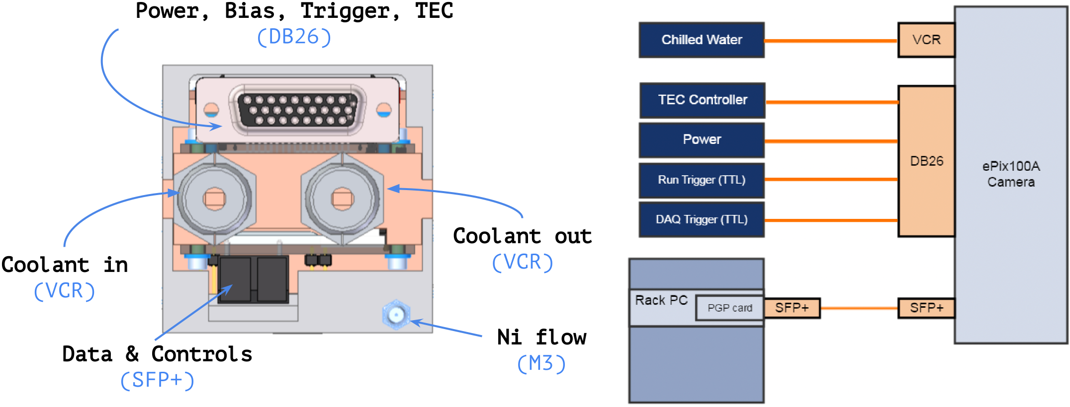
All necessary connections are established in the back of the module, with the connectors depicted below:

The DB26 bus connector and a SFP+ fibre connection transmit all the input and output signals. A single DB26 connector provides power, bias voltage, TTL trigger signals and the temperature feedback and TEC control signal for temperature monitoring and adjustment. The analog signals from the front-end module (sensor + ASICs) are transmitted to the analog board where they are digitized. After digitazion, data is transfered to the digital board and subsequently o a rack-mounted host computer over fibre optics and through a patch panel.

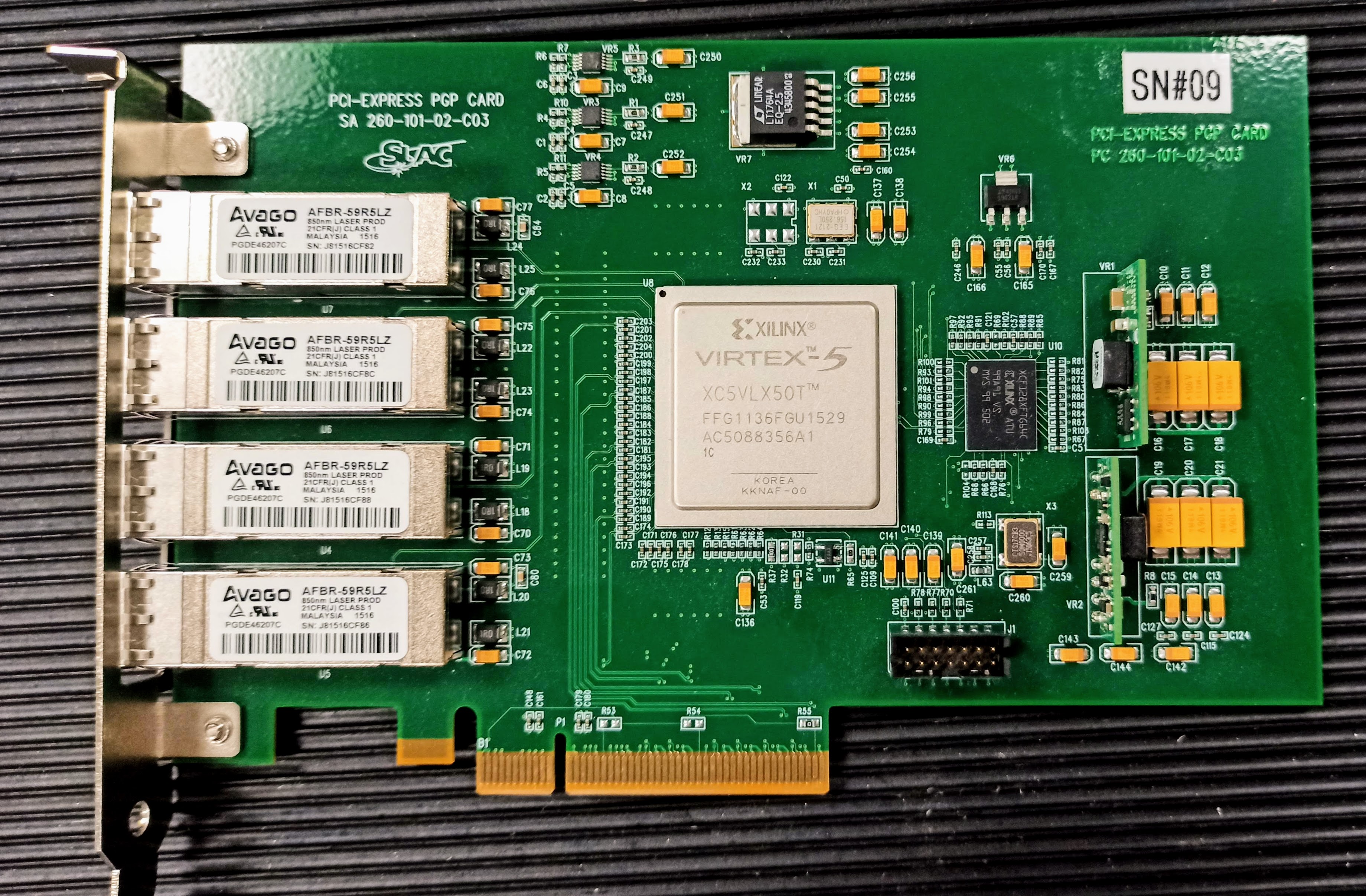
Communication between the digital board and the host computer is established via the SLAC Pretty Good Protocol (PGP) [2], and requires the installation of a PCIe PGP card (depicted below) on the host. Each PGP card can communicate with up to 4 ePix100 modules, so the same host is used to control and receive data from both ePix100 detectors at MID.

References
| [1] | G. Blaj, et al. X-ray imaging with ePix100a: a high-speed, high-resolution, low-noise camera, Hard X-Ray, Gamma-Ray, and Neutron Detector Physics XVIII. Vol. 9968. SPIE, 2016. |
| [2] | Pretty Good Protocol (PGP) |