Operation
This section summarizes the fundamental requirements and procedures for operating the ePix100 detector.
Cooling
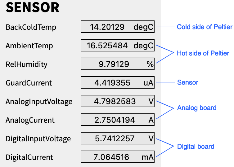
A thermoelectric cooling (TEC) module (Peltier TE-127-1.4-1.5, TE Technology, Inc.) is coupled to the detector head, capable of cooling the sensor down to -15°C. Pins 23/14 on the DB26 connector are connected directly to a spare thermistor which is used for fast temperature monitoring and adjustment via a PID (Proportional-Integral-Derivative) TEC controller, namely the Thorlabs TED4015. The cold side of the Peltier element is in contact with the sensor and ASIC assembly while the hot side is in contact with the camera body. The ePix100 provides readings of both the hot and cold side temperatures which should be continuously monitored for safe operation. A relative humidity reading from the hot side is also featured, to be able to precisely calculate the dew point.
Water cooling is used in parallel, supplied via the VCR connectors in the back, to dissipate the heat arising from the hot side of the Peltier element and the analog and digital boards. The detector body temperature measured from the hot side of the Peltier should be maintained within the recommended operational range of 15–25°C.
To avoid condensation on the sensor plane when operated in air, a constant flow of nitrogen should be provided via the M3 barbed fitting also present in the back. Nonetheless, TEC voltage and current must be set so that the operating temperature is above dew point. If providing a nitrogen flow is not possible, the cold side of the Peltier should not be cooled below 15°C.
Vacuum compatibility
The ePix100 is vacuum compatible and can be operated in vacuum down to 10-6 Torr. When used in vacuum, nitrogen flow is not necessary.
Trigger
Two independently processed triggers (RUN and DAQ) must be provided (also via the DB26 connector), both consisting of a +3.3 V TTL signal with a minimum pulse width of 100 ns. When the detector processes the RUN trigger, its front-end electronics start the acquisition of one image. The DAQ trigger, if received within 100 µs of the RUN trigger, triggers the back-end system to read out the image. To assist with the timing synchronization, a software delay can be configured between the arrival of the external triggers and the start of the firmware procedures. An External Trigger Adapter (ETA) box is used to provide both triggers to the detector, controlled by the Karabo devices MID_EXP_EPIX-[1,2]/TSYS/RUN_TRG and MID_EXP_EPIX-[1,2]/TSYS/DAQ_TRG.
Powering Procedure
Before powering the ePix100, make sure the water pipes are connected and the chiller is running (MID_EXP_CHILL-3/CHILL/CTRL). This can be easily checked in Karabo in the top of the EPIX[1,2] scene of the MID_EXP_EPIX project (see image below). The chiller temperature setpoint is typically 16°C, and the bath temperature read should be continuously updating. On the top left side of the scene, the H2O Flow sensor (MID_EXP_CHILL-3/ASENS/FM5) should also continuously update with a value around 4.4. If there is no flow, the displayed value is 4.

The TEC controller (Thorlab TED4015) should also be switched on before powering the detector. The bottom-left button on the front panel powers the TED4015 and the centre button starts the Peltier. If the DB26 cable is connected to the detector, it should readout a temperature. Each ePix100 has its own TEC controller, the Karabo devices are MID_EXP_PI/TCTRL/TED_EPIX[1,2].
Powering ON
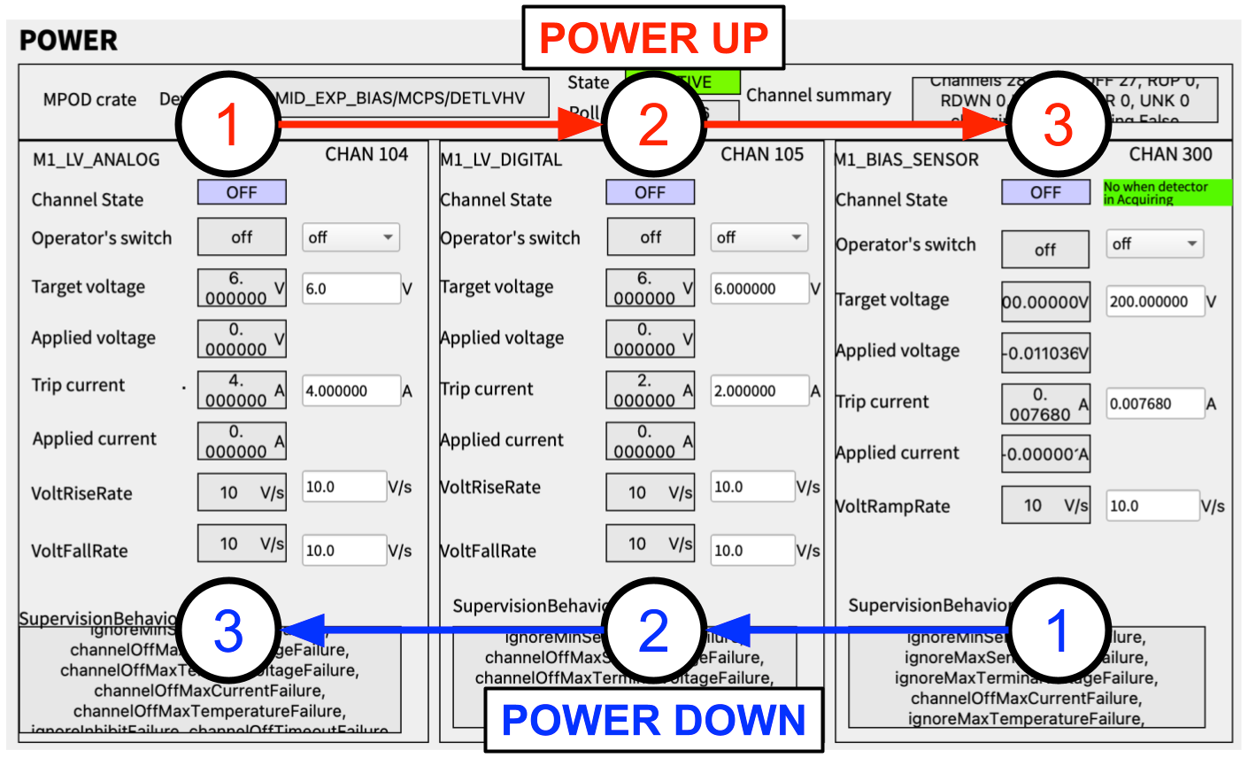
After the checks above are performed, the detector may be powered. For each ePix100, two low-voltage channels (one for the analog and one for the digital board) and a high-voltage to bias the sensor are needed. Are all supplied using the MPOD crate MID_EXP_BIAS/MCPS/DETLVHV. The used channels are listed in the table below:
| Board | Channel | Signal | Specs |
|---|---|---|---|
| WIENER MPV8016 | U104 | EPIX-1 Analog LV | 4.5 - 6.6 V, 4 A max |
| WIENER MPV8016 | U105 | EPIX-1 Digital LV | 4.5 - 6.6 V, 0.6 A max |
| WIENER MPV8016 | U106 | EPIX-2 Analog LV | 4.5 - 6.6 V, 4 A max |
| WIENER MPV8016 | U107 | EPIX-2 Digital LV | 4.5 - 6.6 V, 0.6 A max |
| ISEG E08F2 | U300 | EPIX-1 Bias HV | 20 - 200 V, 250 µA max |
| ISEG E08F2 | U301 | EPIX-2 Bias HV | 20 - 200 V, 250 µA max |
Each ePix100 is powered using the POWER section of their main scene (EPIX[1,2] in project MID_EXP_EPIX). Below is shown the example for EPIX-1, but both scenes are identical.

As suggested by the figure, the power-up procedure is as follows:
- Make sure MPOD device (MID_EXP_BIAS/MCPS/DETLVHV), and the detector controller (MID_EXP_EPIX-[1,2]/DET/CONTROL) and receiver (MID_EXP_EPIX-2/DET/RECEIVER) are instantiated
- Switch the Operator’s Switch of the Analog LV channel to ON. (Keep target voltage and trip current at 6V and 4A)
- Switch the Operator’s Switch of the Digital LV channel to ON. (Keep target voltage and trip current at 6V and 2A)
- Switch the Operator’s Switch of the Sensor Bias HV channel to ON. (Keep target voltage above 20 V). Important: Always use a bias voltage within the operating range (20-200 V). Biasing below 20 V may damage the ASICS. Do not supply low voltage for long times without biasing the sensor.
Wait a few seconds in between steps 1, 2 and 3, to give time for the voltages to settle.
The detector is now ready to acquire images. As soon as the Digital LV is provided, the detector feedback metrics on the left part of the scene should start updating. These can be monitored to guarantee the safe operation of the detector.

Powering OFF
To power off the detector, the inverse order of the power-on procedure should be carried out:
- Switch Sensor Bias HV channel to OFF. Wait until the feedback Applied Voltage feedback value from the MPOD is close to zero.
- Switch Digital LV channel to OFF.
- Switch Analog LV channel to OFF.
The MPOD boards are configured to ramp down (and up) the voltages, so simply switching the Operator’s Switch is safe.
The detector should not be left running for long periods unsupervised. If the detector is no longer being used, it should be powered off.