3. Integrator Processing Module
The fast ADC application includes, per ADC channel, an integrator processing module that can calculate the peak values of periodic ADC signals, or can be configured to integrate based on the current bunch pattern as described in the Bunch Pattern Decoding section. Each module can be individually configured. The following functionalities are available per ADC channel.
3.1. Convert data to voltage units
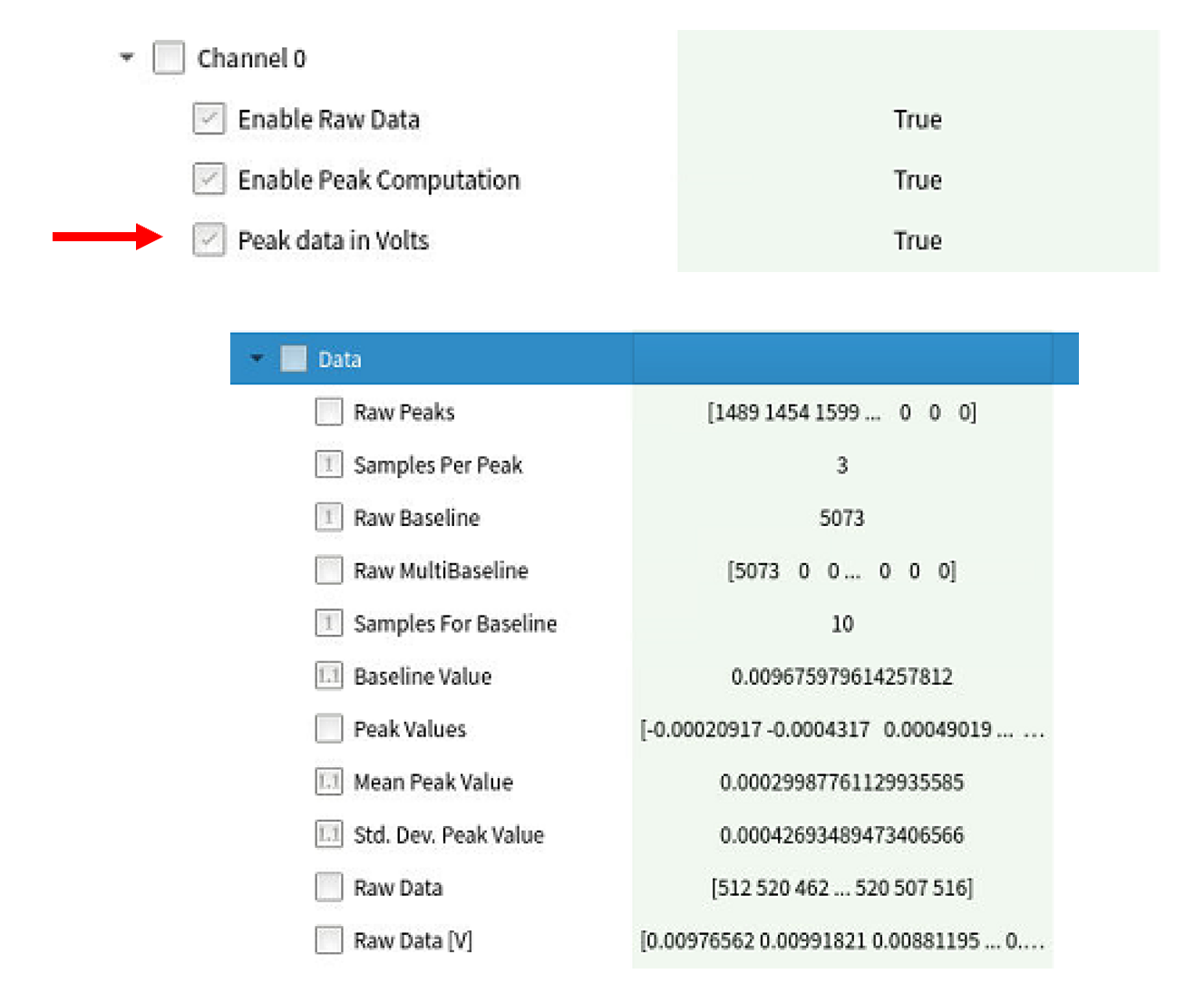
Per channel, the Raw and Peak Integration data can be displayed in Voltage levels in Karabo, which taking into account the ADC Range configuration. Take note that the raw values are always saved in the DAQ.
3.2. ADC Alert
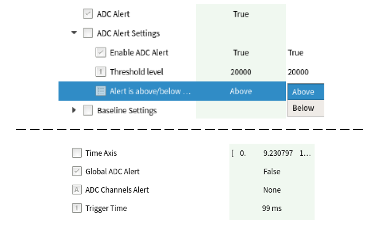
An ADC alert can be configured per channel, which will be raised if the ADC signal goes above/below the user-specified threshold. To clear the alert, either disable it or reconfigure the threshold.
There is a Global ADC alert property which is true if any ADC channel alert is raised. To see which channel raised the alert, check the values in ADC Channels Alert.
3.3. Signal Integration
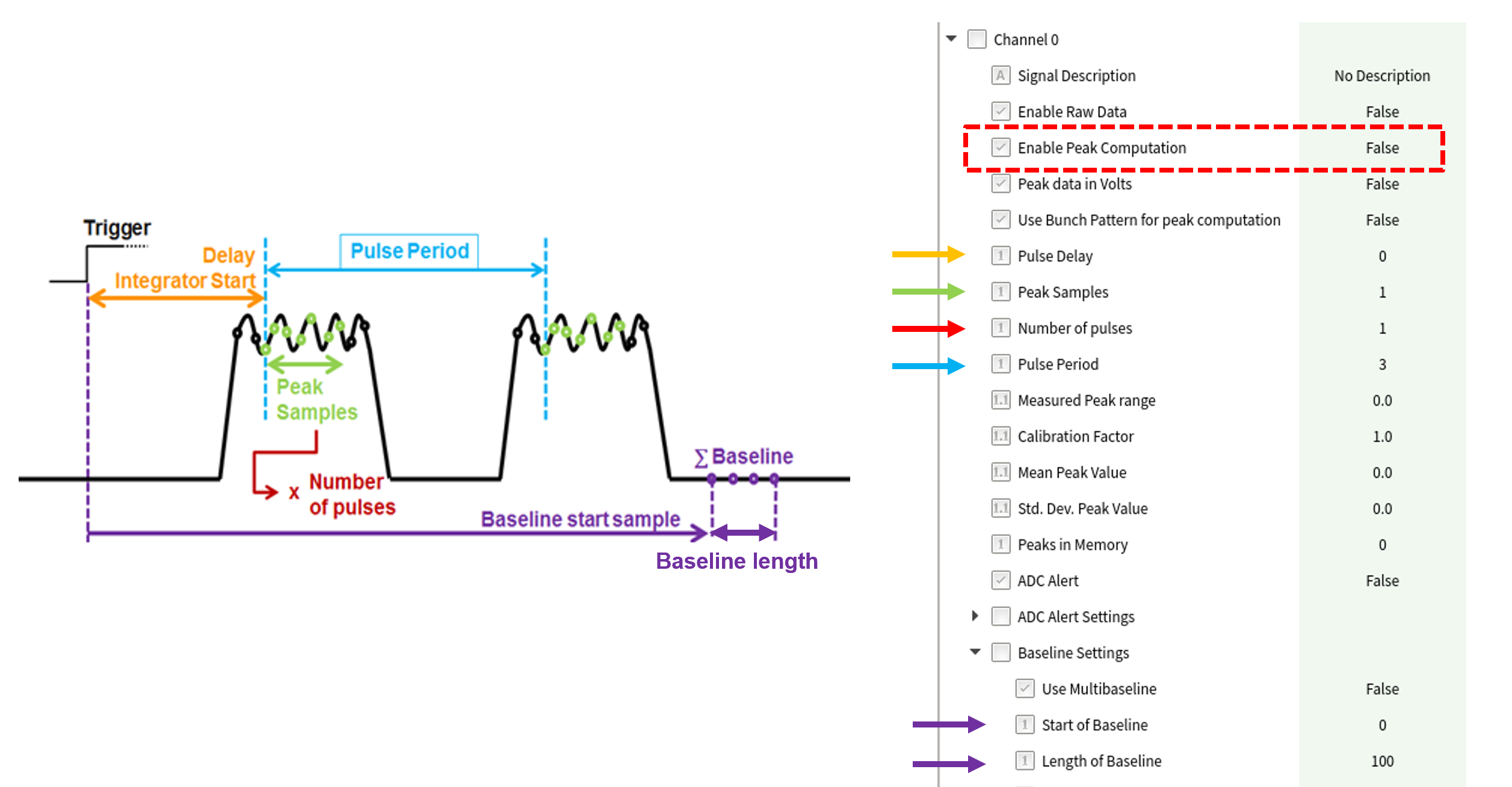
To enable an Integrator module for a specific ADC channel, Enable Peak Computation must be set to True for that channel. Once enabled, the module waits for a trigger signal to start the calculation.
Peak signal calculation starts with the sample where the trigger signal is detected. It is possible to delay the calculation by a specific amount of data samples, by writing the desired value in the Pulse Delay property. For each peak, the module sums up as many ADC samples as specified in the Peak Samples property. The Number of pulses property configures the number of pulses to process after receiving a trigger, while the Pulse Period property specifies the number of samples expected between pulses (thus disentangling between pulses).
The calculated values are available in the output channel Channel X > Output > Schema > Data. Basic statistics are calculated in Karabo based on these values, including the mean and standard deviation of the peak values. The hardware also provides Max. ADC Sample vector, which contains the sample with highest (absolute) ADC value for each integrated peaks.
Another hardware calculated value, which is not saved in the output channel, is the Measured Peak range (located below the Pulse Period parameter). This value shows the difference (in counts or voltage) between the highest and lowest integrated peak.
3.4. Baseline Configuration
The integrated values and statistics are calculated taking into account a baseline value. Multiple options for this value are available in the Baseline Settings node.
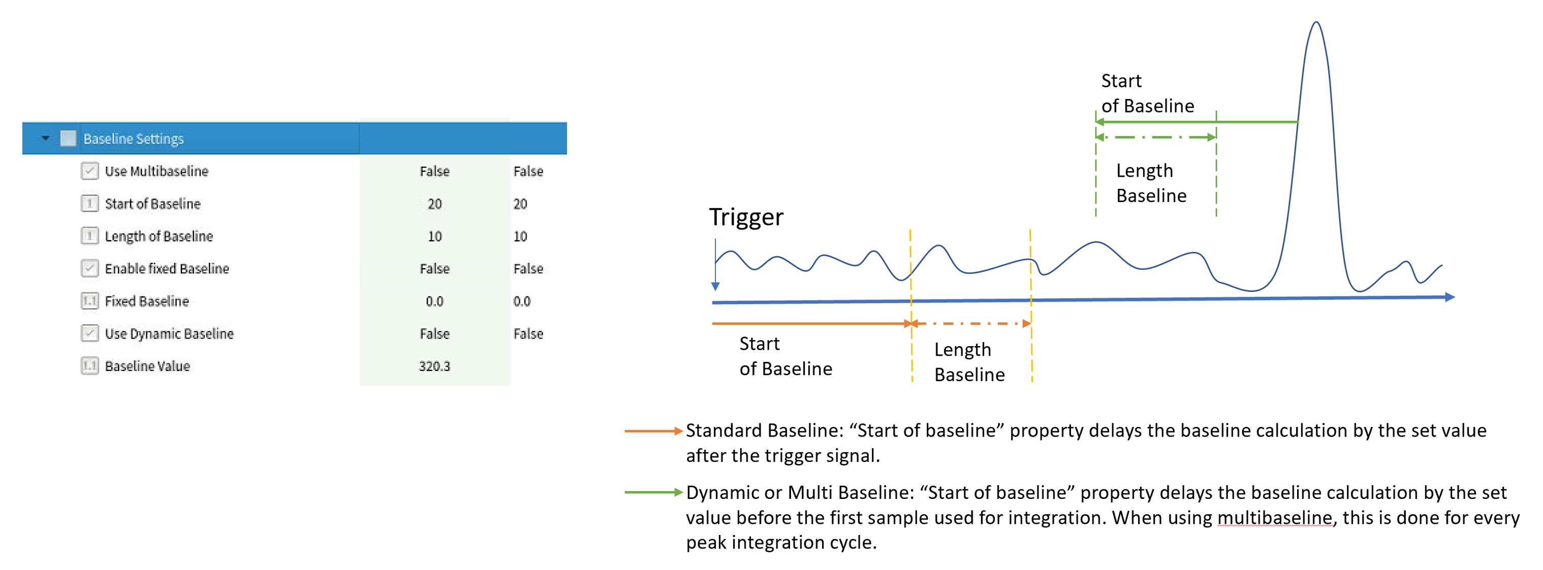
If a fixed baseline is desired, the value of the baseline should be input in the Fixed Baseline property, and the Enable fixed Baseline boolean should be set to true. Otherwise, the baseline will be calculated over a section of the signal.
A signal based Baseline can be calculate in the following ways:
- Standard ::
- A single baseline value is calculated for the entire train. The Start of Baseline value delays the baseline calculation by a set value after the trigger signal.
- Dynamic ::
- This setting is only available when using Bunch Pattern for Integration (see Bunch Pattern Decoding section). A single baseline value is calculated for the entire train. The Start of Baseline value delays the baseline calculation by a set value before the Sample First Bunch.
- Multi value ::
- A baseline value is calculated for every pulse integrated. The Start of Baseline value delays the baseline calculation by a set value before the first sample used for integrated the pulse.
3.5. Moving Average
The fast ADC firmware implements, per ADC channel, a 128 step moving average filter. The output of this filter, available in the Moving average settings node under the name Moving average, gives an indication of the order of magnitude of the ADC baseline value. To enable this filter, Enable Moving average must be set to ‘1’.
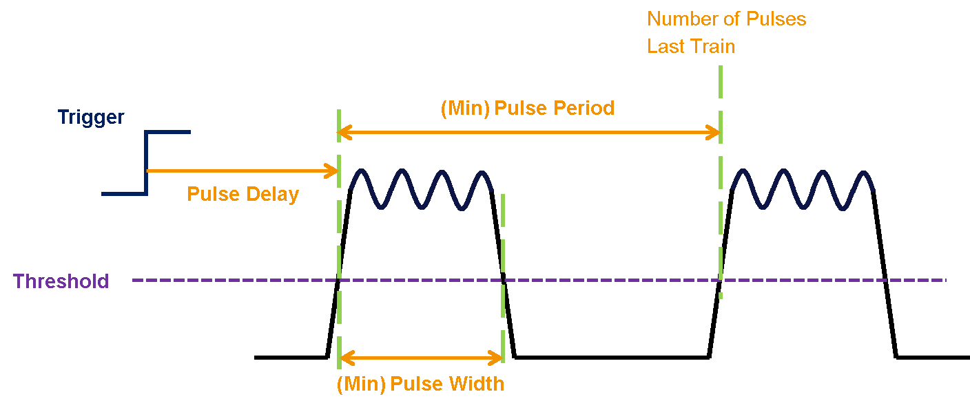
The firmware also provides values concerning the latest train of pulses received, which are referred to as train statistics. These values get updated whenever a new trigger signal is received. The calculated values are:
- Pulse delay (number of samples between trigger and first pulse),
- Minimum pulse width (in samples),
- Minimum pulse period (in samples),
- Number of pulses in last train.
and are presented in the figure here below:
To calculate these values, the moving average filter must be enabled and a threshold value configured in the ‘ADC Threshold magnitude’ property. Whenever the ADC signal goes above or below the threshold value (depending on whether the Moving average value), the firmware starts calculating the aforementioned values.
