Device Initialization
jjAttenuator is a Karabo middlelayer device controlling primarily the four linear motors, one per rod, moving the absorber arm. The control is done by connecting jjAttenuator to the karabo device controlling the corresponding motor of the SAA, and described by the karabo class BeckhoffSimpleMotor.
Before initializing the device, it is mandatory to set in the configuration editor the address of the four motor devices (property “Address Rod N”), which will be connected at initialization. In case of the SAA installed in the SPB instrument line the four devices are shown in Fig. 1.

Fig. 3 Fig. 3 The address of the four linear motor devices moving the absorber arms in SPB instrument line.
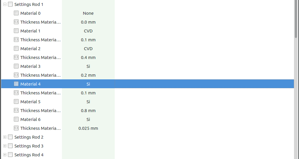
In the property “Settings Rod N” the user should configure (according to the correct information received by the beam scientists) the absorber material (“Material N”) and thickness (Thickness Material N) for every available slot in the absorber arm, Fig. 4. The four absorbing materials Aluminium, Boron Carbide \(B_4C\), CVD (synthetic) diamond, and Silicium are currently available. Note that the first slot should be left set to “None” and “0 mm”, corresponding to the section of the upper section of arm with no absorber. When the arm is configured to have the beam going through its upper aperture, it will provide no attenuation to the beam.

Fig. 4 Fig. 4: The user must select the type of material and thickness for each of the six absorbers.
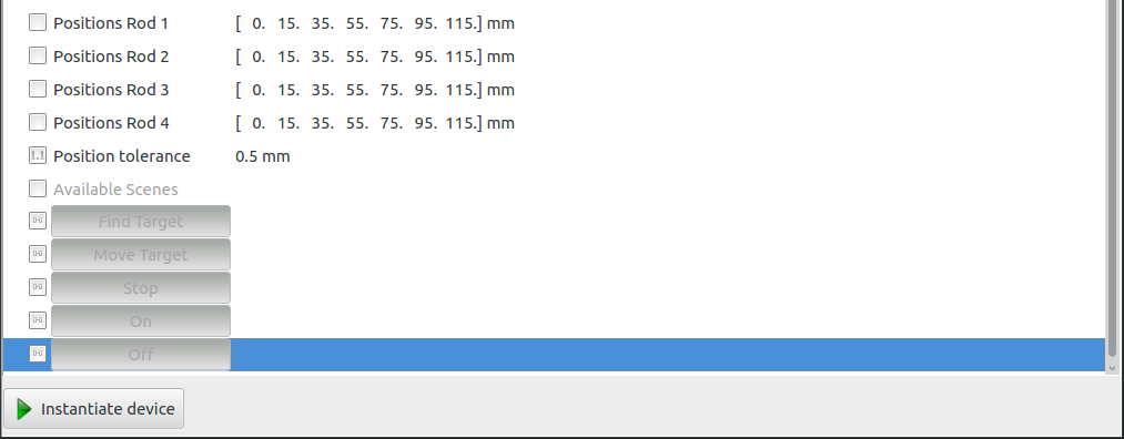
The user can change the position of the absorber slots in the rod (“Positions Rod N”), Fig. 5, to properly longitudinally move the arm in order to have a desired absorber in the beam. The default values, provided by the SAA responsible, are hard-coded. It is clear that any change of the default values should be done under the supervision of the detector responsible. Also, the total transmission coefficient (“Transmission”) is visible.

Fig. 5 Fig. 5: Before initialization the user can change the position of the absorbers along the motorized arm.
At initialization, the linear attenuation coefficient \(\mu_E\) for different values of incoming x-ray beam energy \(E\) is loaded from look-up files and for the four materials. Additionally, the transmission coefficient \(T_E\) per all possible values incoming beam energy [*] and for all the configured absorbers is determined according to the Beer-Lambert law
with \(d\) being the thickness of the absorber. Every time a beam energy value (“Actual Energy”) is selected by the user, the corresponding subset of the transmission coefficient array is considered. The property “Energy tolerance” is considered when a new beam energy value is inserted. When the new value is consistent within the tolerance with the current one then the transmission coefficient subset is not changed.
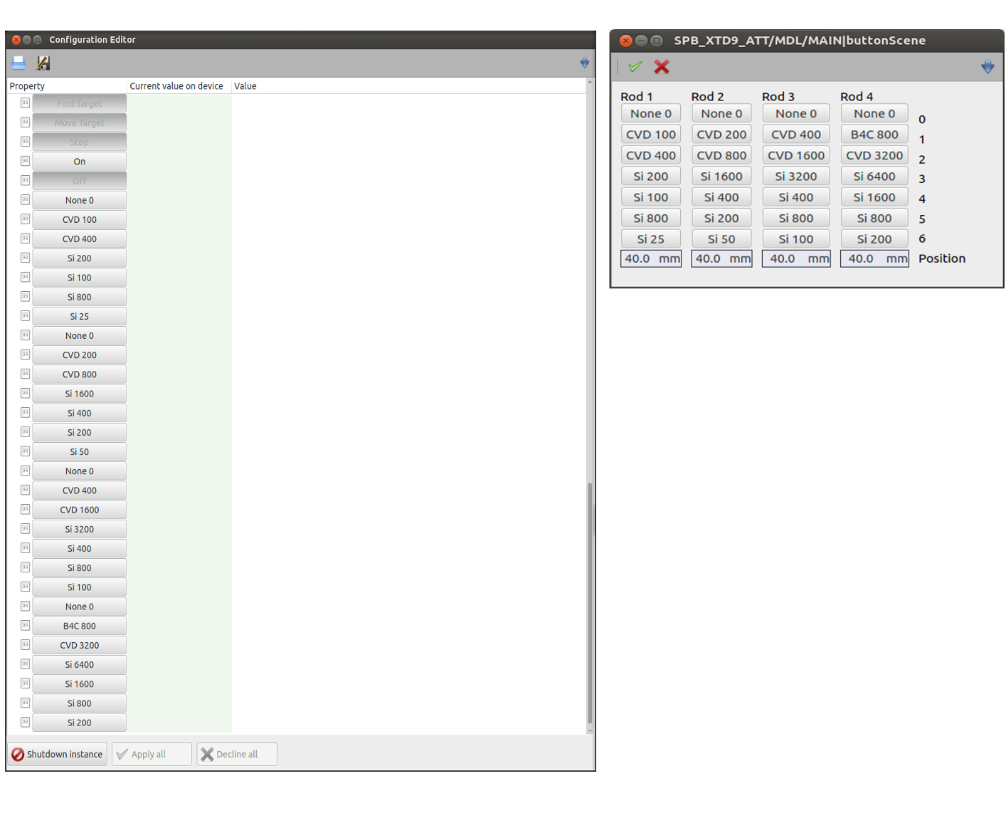
During initialization the buttons to positions the arms to one of the available positions of the absorbers (as configured by the user) will be created in the configuration editor. This allows the user to manually position the arms according to his needs, left panel of Fig. 6:

Fig. 6 Fig. 6: From the configuration editor and from the device scene the arms can be manually set to positions specific to a desired absorber and thickness, left and right panel, respectively.
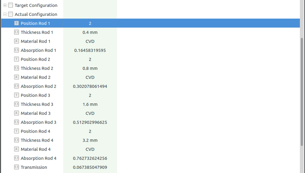
A continuous monitoring of the four motor positions is eventually launched. The property “Position tolerance” is used when finding out whether the arm position is centered with respect to one of its absorber slot (according to the positions set bu the user); This procedure is performed whenever the expected beam energy is changed or when one arm is longitudinally moved. An example of detector with absorbers correctly centered in the beam is presented in Fig. 7. Here, the current position of each rod (“Position Rod N”), the corresponding centered absorber (“Thickness Rod N”) and absorption factor (“Absorption Rod N”) are shown.

Fig. 7 Fig. 7: The current status for each arm is available to the user.
Footnotes
| [*] | Here, since the input look-up data are not fine grained enough, the data-set is smoothed according using spline techniques. This enables to perform calculation also for surrounding energy values. |