4. The pnCCD Hardware
4.1. Overview
One of the six experimental stations at European XFEL is the SQS (see Acronyms for a list of acronyms) instrument. It focuses on the investigation of fundamental physical processes by studying interaction of light with matter using low-energy X-rays. During an experiment with the SQS instrument, soft X-ray flashes are scattered by a sample. A detector downstream the sample is used to study the interactions and store the data as digital images.
This detector is a 1 megapixel pnCCD detector developed by the PNSensor GmbH [1]. It is installed at the SQS instrument in collaboration with Robert Hartmann (from PNSensor GmbH) together with the detector group from European XFEL. In this chapter, the hardware of this detector is briefly summarized. The pnCCD detector discussed in this manual is the one installed and commissioned in August 2020. The serial numbers of this detector are: 205 (top sensor) and 206 (bottom sensor).
4.2. The 1 Megapixel pnCCD Detector at European XFEL
Detailed information on the pnCCD detector at European XFEL (see Fig. 4.1 and Fig. 4.2) and its concept can be found here and in this paper.
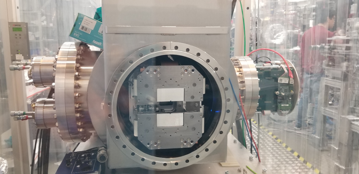
Fig. 4.1 The pnCCD camera at European XFEL mounted on its chamber before being mounted on the beamline. The protective shields (white pieces) are still attached.
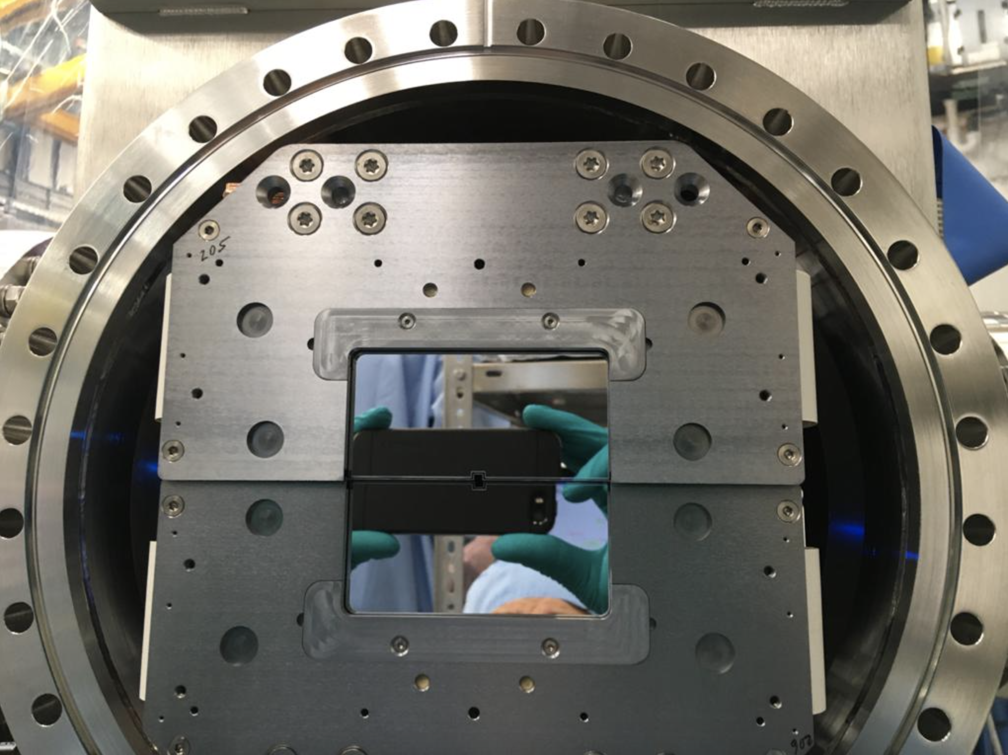
Fig. 4.2 A close-up view of the pnCCD camera at European XFEL. The protective shields are removed.
The pnCCD detector at European XFEL is a pixalated 2D imaging detector with 1024 \(\times\) 1024 pixels, each 75 \(\mu m \times\) 75 \(\mu m\) in size. The detector consists of two identically designed, both back illuminated, fully depleted monolithic pnCCD chips, which are completely independed modules (each being a separate sensor). The entire active area of the detector spans 78 \(\times\) 78 \(mm^2\). This detector has a very high quantum efficiency (\(> 80\%\) at 0.7 – 12 keV) and very low readout noise (\(3e^-\) rms at high gain). It is capable of detecting photons with an energy range of 0.3 – 25 keV. pnCCD is capable of counting single photons in the full energy range of the SQS instrument (0.2 – 8 keV) while maintaining a high dynamic range (up to 1500 at 1 keV). Table 4.1 summarizes the characteristics of the pnCCD detector.
| Property | Value |
| Photon energy range | 0.3 – 25 keV |
| Detection efficiency | \(> 80\%\) for 0.7 < \(E_{\gamma}\) < 12 keV |
| Number of pixels | 1024 \(\times\) 1024 |
| Pixel size | \(75 \mu m \times 75 \mu m\) |
| Detector size | 78 \(\times\) 78 \(mm^2\) |
| Dynamic range | up to 1500 at 1 keV |
| Resolution | Single photon (SQS full energy range) |
| Readout noise | \(3e^-\) rms (at high gain) |
| Frame rate | 150 Hz |
| Central gap | 2 mm |
| Distance to focus | 50 – 350 mm |
| Vacuum compatibility | \(< 10^{-8}\) mbar |
Since the flux of the European XFEL beam on the detector may be too high, a central hole is required for the beam to pass through. As mentioned previously, the pnCCD detector consists of two completely independent modules, where each single pnCCD chip has a format of 512 \(\times\) 1024 pixels. Each pnCCD sensor (module) has a central hole cut out of it by laser. The dimension of this hole is 22 pixels vertically by 60 pixels horizontally (see Fig. 4.3). Such a layout permits the placement of the two movable pnCCD detectors around the X-ray beam to cover a larger angular range. Each module can be moved horizontally, vertically and along the beam direction independent of one another. The size of the central gap, as well as the distance of the detector plane to the focal point of the SQS instrument can therefore be varied.
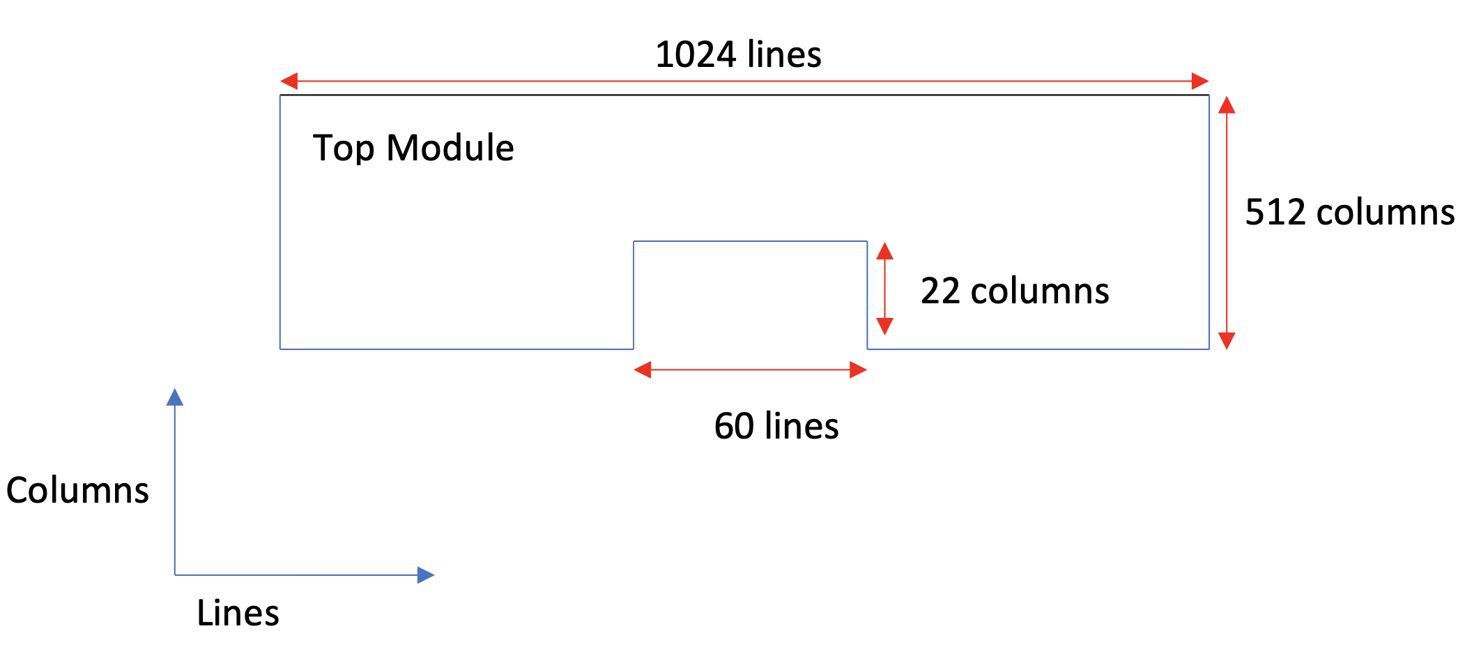
Fig. 4.3 Depiction of the laser-cut central hole in the top pnCCD sensor. The bottom sensor is the same only inverted with respect to the lines axis.
4.3. In-Vacuum Electronics
4.3.1. CAMEX ASICs
During the readout process, the charge from each pixel generated by the X-ray photons is transferred, using shift registers, line by line along the pnCCD transfer columns to the readout at the end of each column (see Fig. 4.4 and Fig. 4.5). Each column is terminated at both ends of the detector by a charge collecting anode connected to an integrated n-channel JFET. The latter is an on-chip amplifier bonded to one input channel of the CAMEX ASIC. Thus, the raw signal is pre-amplified by these JFETs. Each pre-amplifier feeds its signal into the CAMEX ASIC for that column. The basic architecture for all CAMEX readout chips (see this paper) is the column parallel readout of the detector. Thereby, having a large number of channels working in parallel to amplify and filter the signals and then multiplex these to an external ADC. Such column-parallel signal transfer and amplification allows high frame rates in combination with low noise performance.
In total, 8 CAMEX ASICs with 128 inputs each are required for handling the signal of the 1024 JFET outputs of each pnCCD chip. The CAMEX ASICs perform further signal processing by providing two-stage amplification, filtering, noise band width limitation, and line driving. Finally, the signal is stored in a sample and hold register. The output, i.e., 128 channels, is then multiplexed after the signal processing with typically 10 MHz per CAMEX output node to an external ADC.
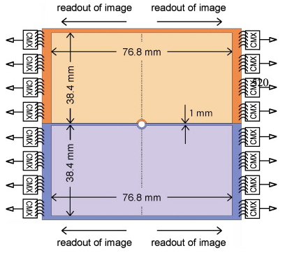
Fig. 4.4 Depiction of each pnCCD chip with 512 \(\times\) 1024 pixels shown in orange and purple. The collected charge in each chip is independently transferred to the right (512 \(\times\) 512 pixels) and to the left (512 \(\times\) 512 pixels) with the indicated device divider in the center. There is no insensitive gap between the two 512 \(\times\) 512 pixels units. All columns are shifted and processed in parallel. Every 128 CCD columns (equivalent to the horizontal rows in a matrix) are connected to one readout CAMEX (shown as CMX in the figure). The charge is transferred line by line (the CCD lines are equivalent to the vertical columns in a matrix) from the center of the CCD towards each end along each column.
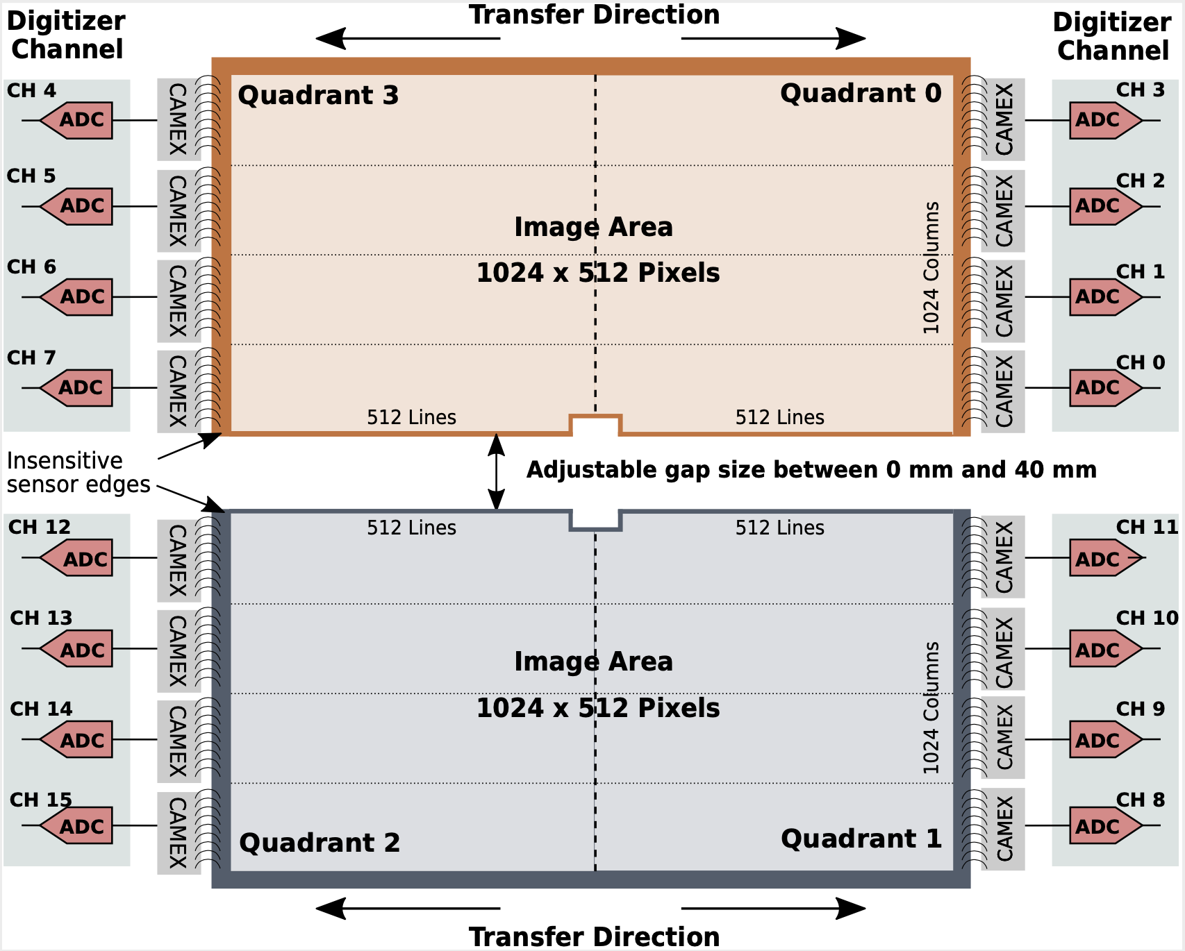
Fig. 4.5 Schematics of each pnCCD chip. Figure courtesy of Markus Kuster (European XFEL employee).
4.4. Front-End Electronics
The control electronics, sitting outside the vacuum, consist of i) a sequencer, data pre-processor, data acquisition, and the power supplies, which are put together in a 19-inch-compatible cPCI-based modular unit (see Fig. 4.8 and here and also this paper), as well as ii) two FastADC boards (see Fig. 4.7 and Fig. 5.11). For more detailed discussion on these electronics, please refer to this paper. The pnCCD electronics rack is shown on Fig. 4.6.
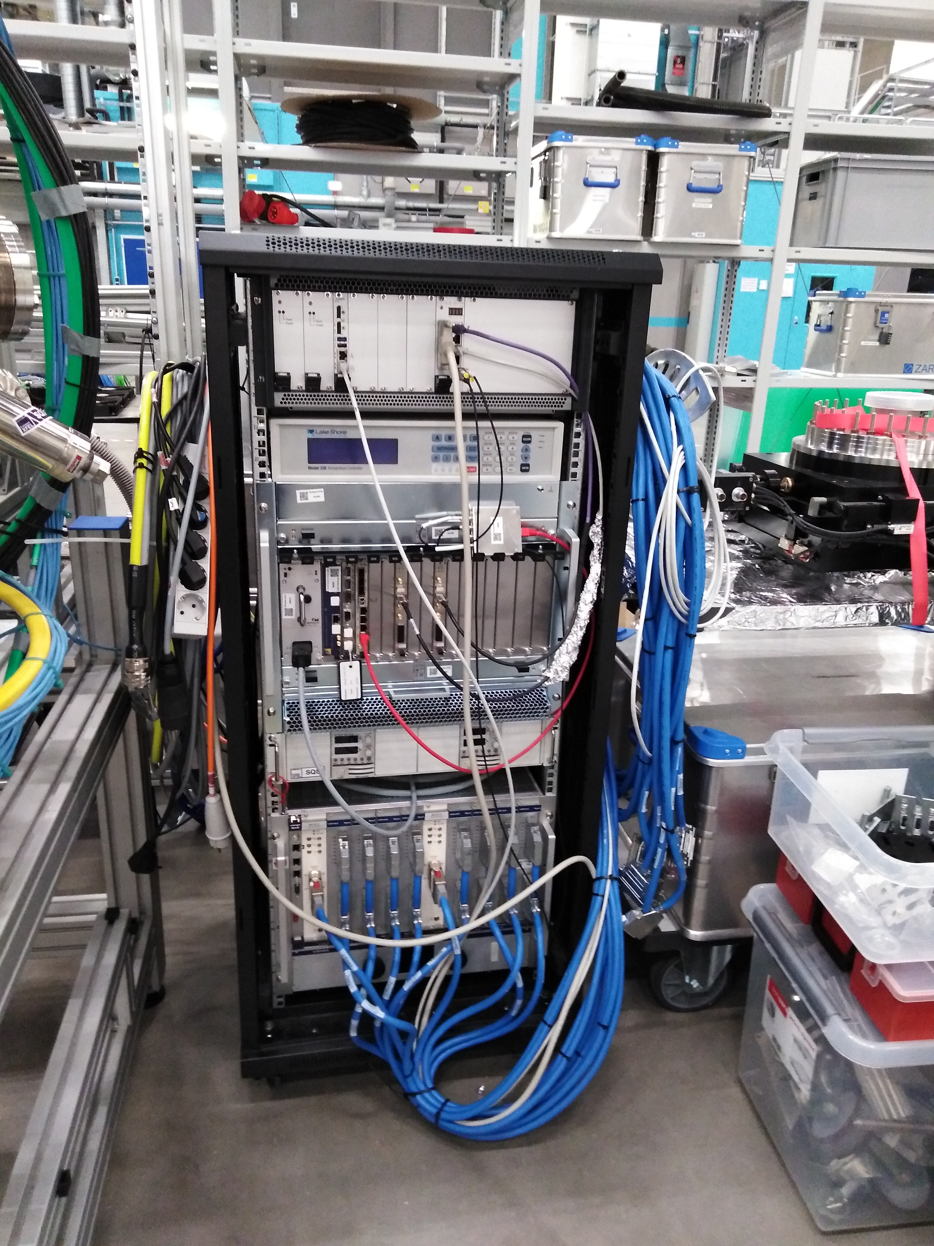
Fig. 4.6 The pnCCD electronics rack, which needs to be properly grounded. From top to bottom: sequencer, Lake Shore unit, trigger box (small square box), \(\mu\!\) TCA.4 crate with the FastADC digitizers, an auxillary power supply with two power outputs, and the MPOD crate.
4.4.1. FastADC Digitizers
After serialization by the CAMEX, the analogue signal is transferred to and digitized by two SIS8300 digitizer boards (see Fig. 4.7 and Fig. 5.11) providing 10 ADC channels with 16 bit resolution each. These FastADC boards are plugged into a \(\mu\!\) TCA.4 crate and digitize the analog signals sampling them with a frequency between 10 MHz and 125 MHz per channel.
Application specific readout, data formatting, data reduction and processing algorithms can be implemented on a Virtex V FPGA available on each FastADC board. Each board further digitizes the pixel clock signal provided by the timing sequencer of the pnCCD. The digitizer FPGA firmware is configured to sample 800000 Samples per CAMEX and image, as determined by the 10 Hz train trigger, which corresponds to 1 or 2 samples per pixel and readout cycle. The CAMEX is typically operated at 10 MHz, enabling image rates up to 100 frames per second.
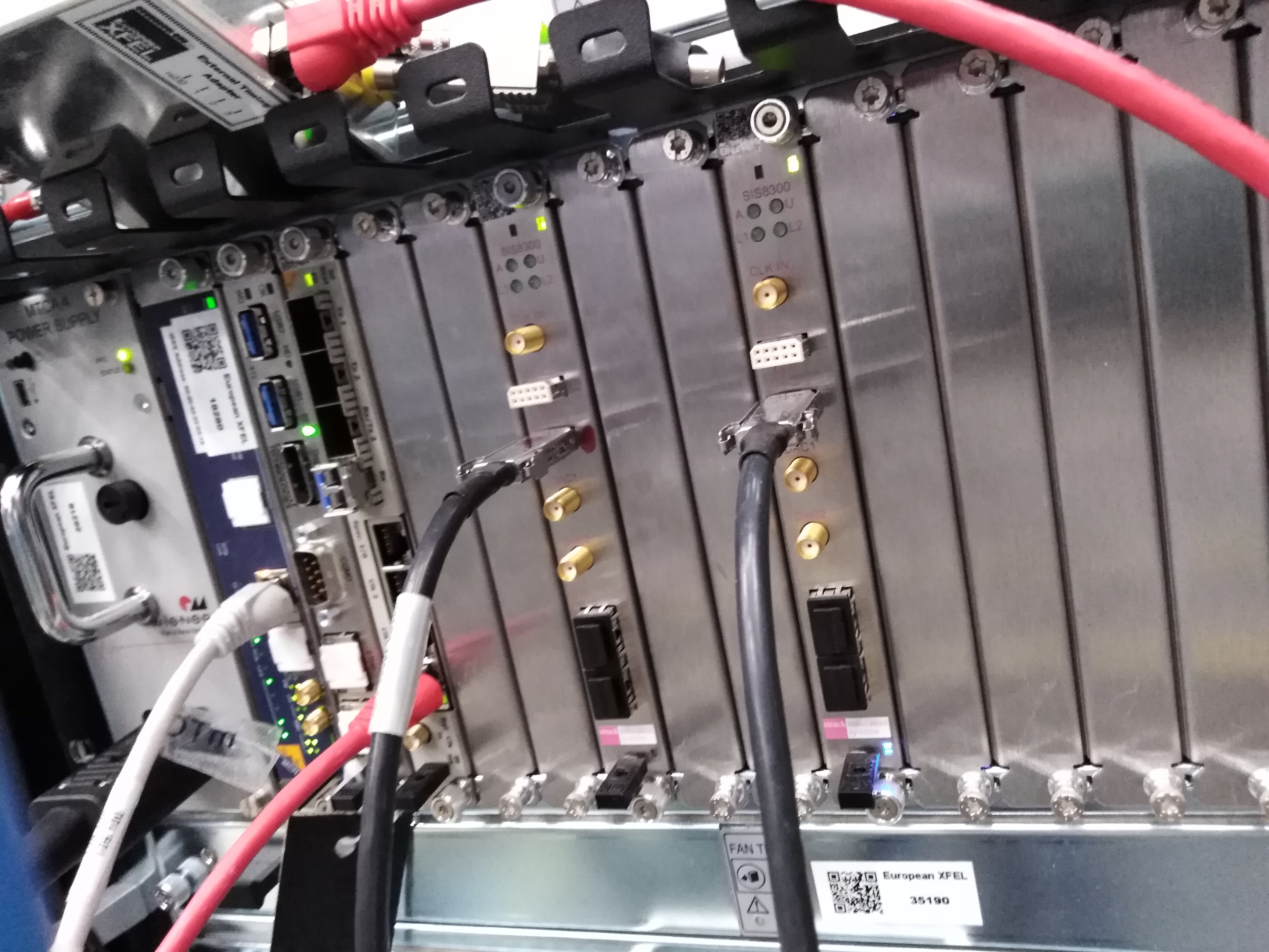
Fig. 4.7 The FastADC digitizers of the pnCCD are the two boards with the SIS8300 label.They are plugged into the front of the pnCCD \(\mu\!\) TCA.4 crate.
4.4.2. Sequencer
The digital sequencer (see Fig. 4.8) controls most of the internal switches, the pixel clock signal, and the integration of bias current DACs. With the DACs, the bias currents of the operational amplifiers can be set for each chip individually.
In general, the pnCCD’s sequencer generates the readout sequence and control signals for the CAMEX and the CCD. The sequencer can be programmed in a very flexible way, such that the CCD’s readout and signal processing sequence can be adjusted to and optimized for specific experimental requirements. Nevertheless, for most scenarios, changing the readout sequence requires a recalibration of the detector.
Through a digital control register with a serial interface connected to the external control system, it is possible to adjust the gain of the pre-amplifiers on the CAMEX ASICs to the experiment conditions. Apart from the highest gain, g = 1/1, gain values of g = 1/4, 1/16, 1/64, 1/256, 1/340 and 1/512 can be configured before data taking.
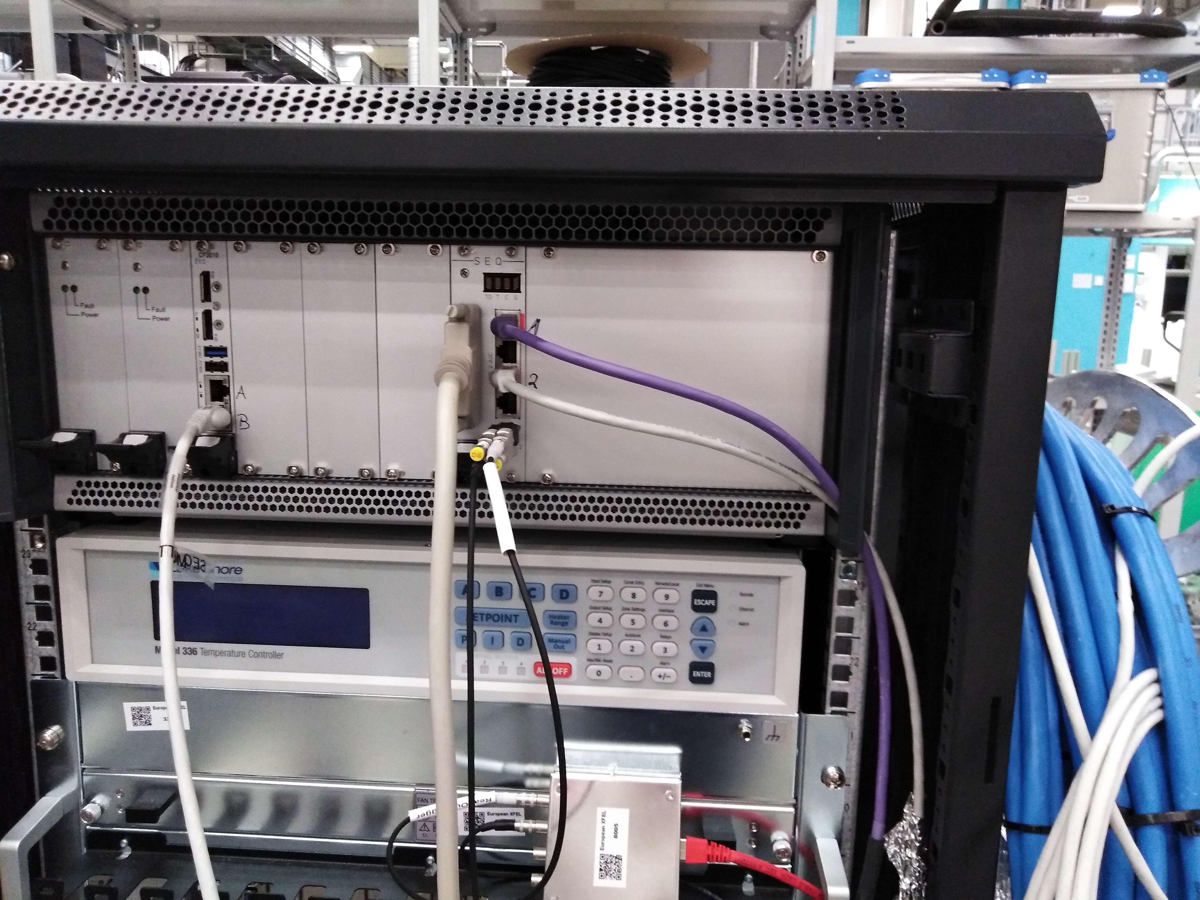
Fig. 4.8 The sequencer module for pnCCD is the top module located above the Lake Shore unit. The cable that is connected to input A is missing in this picture.
4.4.3. Clock and Control
The interface between the detector front-end and the EuXFEL timing system is accomplished through the EuXFEL Clock & Control system, which synchronizes the DAQ and the detector front-end timing to the general EuXFEL facility machine timing system.
The clock and control system is based on a combination of a general purpose \(\mu\!\) TCA.4 AMC board and a custom Rear Transition Module (RTM) board specifically designed to interface the detectors at EuXFEL. The system uses a clock from the timing system in the \(\mu\!\) TCA crate, which is phase aligned with the accelerator. The RTM front-end interface provides the timing signals for starting the detector readout, for individual X-ray pulses in a train and a train stop signal indicating that the bunch train ended. Therefore, all clock signals of the pnCCD, ADC and CAMEX are phase aligned to the timing system and consequently to the accelerator.
Photons being absorbed by the pnCCD between two consecutive readout cycles would create a potential background signal. Therefore, the pnCCD sensor is cleared before the arrival of the first X-ray FEL pulses by quickly shifting residual charges to the readout anode and discarding the charge signal. The clear signal is followed by a signal integration period with a duration chosen according to scientific requirements. Although pulse-resolved data recording is not feasible, it is possible to integrate for an entire pulse train, and reading out at 10 Hz. The final signal readout, amplification, filtering and digitization take additional 15 ms (approximately). The readout sequence is synchronized to the EuXFEL bunch pattern through the SEQUENCER CLEAR TRIGGER and SEQUENCER START TRIGGER signals provided by the clock and control system, respectively. Both trigger signals are exposed to Karabo and can be varied based on scientific requirements.
More details about pnCCD detector is found in this paper.
4.5. MPOD Power Supply
The detector and its in-vacuum electronics are biased using a WIENER [2] MPOD crate (see Fig. 4.9) with: i) eight LV 8030 8-channels 50W modules (4 of these modules per pnCCD sensor) to power up/down the CAMEX ASICs, and ii) two 8016 8-channels 50W ISEG HV modules (one per pnCCD sensor) to power up/down the top and bottom CCDs. The pnCCD MPOD system provides bias voltage for a total of 88 channels.
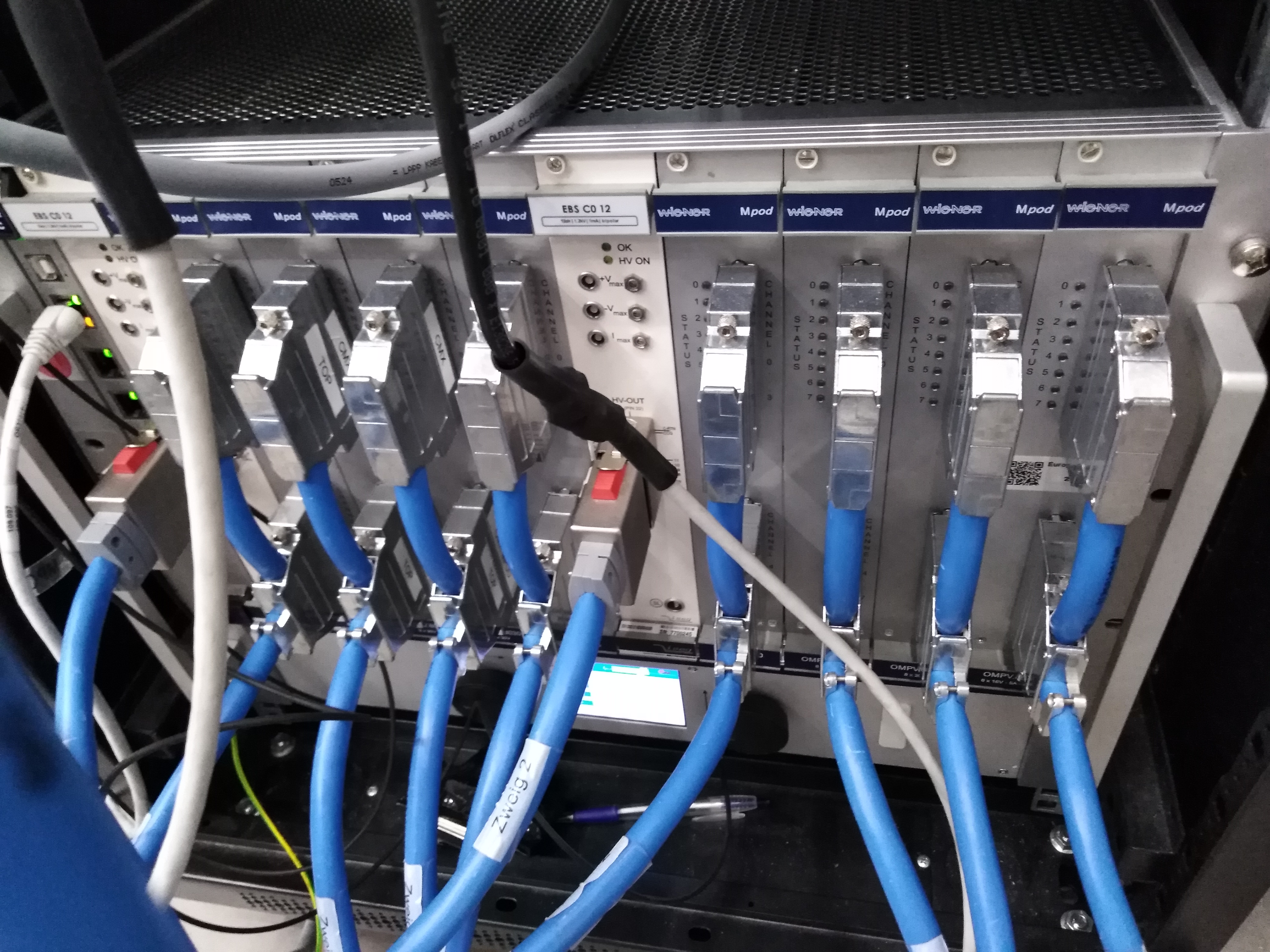
Fig. 4.9 The pnCCD MPOD crate.
For safety reasons, a \(+5V\) signal coming from the relay of the second channel (channel 2) of a Maxigauge (see Interlock) must be present in order to be able to use the MPOD system. The \(+5V\) signal is a crate_enable signal to turn off the MPOD crate in case the pressure measured by the \(P_{CCD, high}\) full range pressure gauge, on top of the pnCCD chamber (see Fig. 4.12), falls outside the allowed range. To provide this signal, the specific aforementioned relay has to be enabled. In the absence of this signal or if the aforementioned relay is disabled, the MPOD system will be interlocked and cannot be turned on. As a result, the CAMEX system and the detector cannot be biased.
4.6. Uninterrupted Power Supply
powering ON/OFF the pnCCD is a sequential process that takes between 10 to 15 minutes. If the power is lost during the ON/OFF powering procedure, the detector can be seriously damaged. To protect the detector when biased, one needs to ensure that the power is continuously provided to the detector. To do this, we use a UPS (see Fig. 4.10), which provides a backup for pnCCD power. In case of a power failure, the UPS will provide the detector with power for a long enough time so that the pnCCD can be powered down correctly going through all the sequences of powering OFF procedure without an interruption to the power.
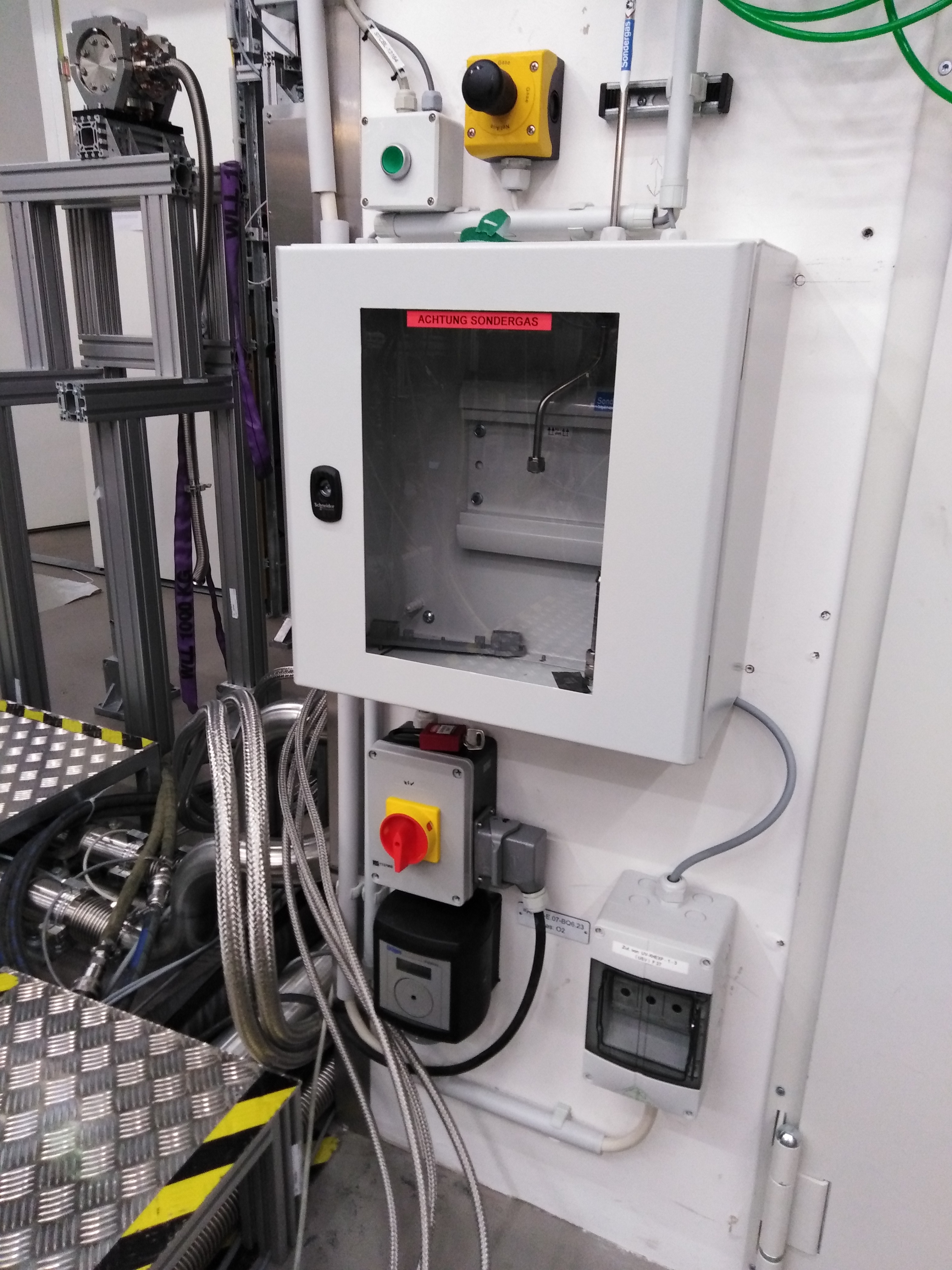
Fig. 4.10 The input to the pnCCD UPS system. The main power cable of the electronics rack of pnCCD is plugged in this unit.
In case of a power failure, the UPS system provides power long enough for a safe shutting down of the detector. However, at the moment, the MPOD crate’s controller is of a model that does not have the ability to power down the LV cards in sequence. Thus, in case of a power loss, all those LV cards will be shut down at the same time, which is not safe for pnCCD because the powering down procedure of pnCCD is a sequential procedure that has to be followed in order. On July 22, 2020, Kai-Eric Ballak (European XFEL employee) has ordered the CC24 card from WIENER for the MPOD crate to ensure that the sequential powering down of the LV cards in the MPOD crate can be achived. This will ensure that the powering down procedure of pnCCD will be performed safely in case of a power loss.
The two chillers of the pnCCD also have their own independent UPS system (see Fig. 4.11). This latter UPS system will provide uninterrupted power long enough for the two chillers to be safely shut down in case of a power failure.
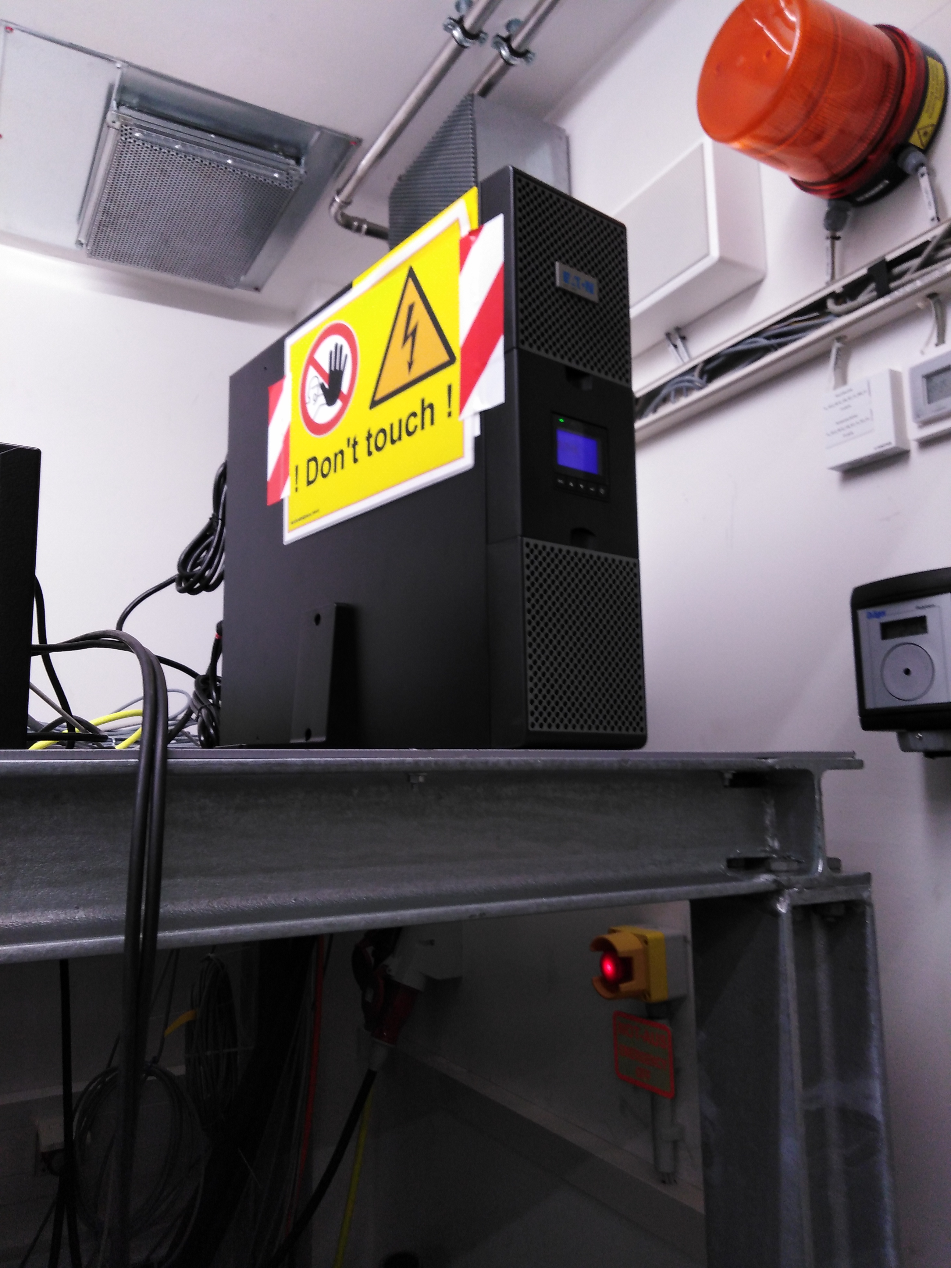
Fig. 4.11 A separate UPS system for the two pnCCD chillers. This unit is located inside the small utility room inside the SQS hutch.
4.7. pnCCD PLC System
A Beckhoff-based PLC system (BKF571 and BKF572) with low voltage components, except the primary power connections, is in use for NQS PNCCD. The PLC is set up by the EEE group in loop 15. The PLC system is used to:
- control the pnccd vacuum and compressed air systems, and monitor the status and measured values of all remote controllable components related to these systems.
- control the pnCCD motion system; monitor the status of the motors and encoders of this system; provide standard and coordinated motion for the two halves of the detector; and allow safe operation preventing collisions between the sensor planes, the sensor planes with the environment, and the focal plane assembly with components of the vacuum chamber.
- control the pnccd cooling system; monitor the status of the boralectric heaters and the Polycold PCC Compact coolers; read the PT-100 temperature sensors; monitor and control the Lake Shore 336 controller providing access to the temperature setpoints and temperature control parameters; and allow switching ON and OFF the boralectric heaters and the Polycold PCC Compact coolers independently.
4.8. pnCCD Vacuum System
The pnCCD detector has its own vacuum system independent of that of the SQS beamline. Fig. 4.12 shows the schematic diagram of the pnCCD vacuum system. Fig. 4.13 shows the 3D CAD model of the vacuum vessel of the pnCCD detector. vacuumEquipement shows pictures of some of the vacuum equipment used for the pnCCD.
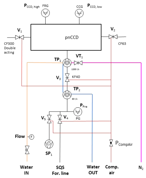
Fig. 4.12 The schematic layout of the pnCCD vacuum system on the SQS beamline. Diagram is taken from this webpage. The turbo molecular pumps are water cooled. Abbreviations: FRG: full range gauge; CCG: cold cathode gauge; For: foreline; Comp: compressed; and PG: Pirani gauge.
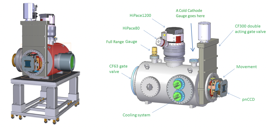
Fig. 4.13 The mechanical design of the pnCCD detector including the vacuum system, motion system and the pnCCD focal plane module mounted on its laboratory setup (left). A schematic view of all the detector system components is shown on the right side.
During the experiments utilizing the pnCCD, its chamber should be operated at \(10^{-8}\) mbar or below. To avoid contaminating the detector and the SQS sample chamber, the vacuum vessel has to be free of hydrocarbons.
The UHV conditions are generated in the detector chamber by two water-cooled turbo molecular pumps: a Pfeiffer HighPace 1200 (\(TP_{1}\) on Fig. 4.12), which is directly attached to the pnCCD chamber, and a Pfeiffer HighPace 80 (\(TP_{2}\)), which backs up the aforementioned pump. A KF-40 gate valve (\(V_{3}\)) separates the two pumps acting as a safety valve in case of a failure of a turbo pump. External Pfeiffer TCP-350 controller controls the Pfeiffer HiPace 80 turbo molecular pump. The Pfeiffer HiPace 1200 pump only requires a main connection directly on the pump and is controlled by a TC1200 controller via RS-485 serial interface. A Pfeiffer full range gauge (\(P_{CCD, high}\)) and a cold cathode gauge (\(P_{CCD, low}\)) are monitoring the pressure of the UHV part of the detector system between \(10^{-11}\) mbar and \(10^{3}\) mbar. A Pirani gauge (\(P_{Pre}\)) provides the pressure status in the pre-vacuum section (separated from the SQS foreline pump by \(V_{4}\)) in the pressure range between \(10^{-4}\) mbar and \(10^{3}\) mbar.
Venting of the detector with dry \(N_{2}\) is possible through the venting valve \(VT_{1}\) attached to the Pfeiffer High Pace 1200 turbo molecular pump (see Fig. 4.12).
The gate valves \(V_{1}\) and \(V_{2}\) (see Fig. 4.12) provide vacuum interface to the experiment and allow operating the detector independently if the detector chamber is removed from the experiment setup, i.e., both valves are attached to the detector vacuum chamber. In addition, these valves act as safety valves separating the detector volume from the experiment chamber in case of, e.g., a vacuum failure on the experiment side.
A pressure switch for monitoring of the compressed air pressure (\(P_{CompAir}\) on Fig. 4.12) is installed at the compressed air distribution. The signal reading is used by the detector interlock system for monitoring the status of the compressed air distribution.
To control the vacuum system, monitor the status and status changes, and read the pressures at different locations of the pnCCD vessel, a Beckhoff-based PLC system is used (see PLC).
The SQS beamline scientists are responsible for and operate the vacuum system.
4.9. pnCCD Cooling System
The cooling system of the pnCCD is based on PCC with boralectric heaters (KH15860 version) [3] controlled via a Lake Shore Cryotronics 336 unit (see Lakeshore).
Each PCC system (see Fig. 4.14) consists of a cryocooler, an air-cooled compressor, and a pair of self sealing supply/return gas lines to link the cryocooler to the associated compressor, which circulate the PT-30 gas refrigerant to the system. Each PCC system has a cooler control unit (see Fig. 4.15). The latter is designed to turn ON/OFF the chillers.
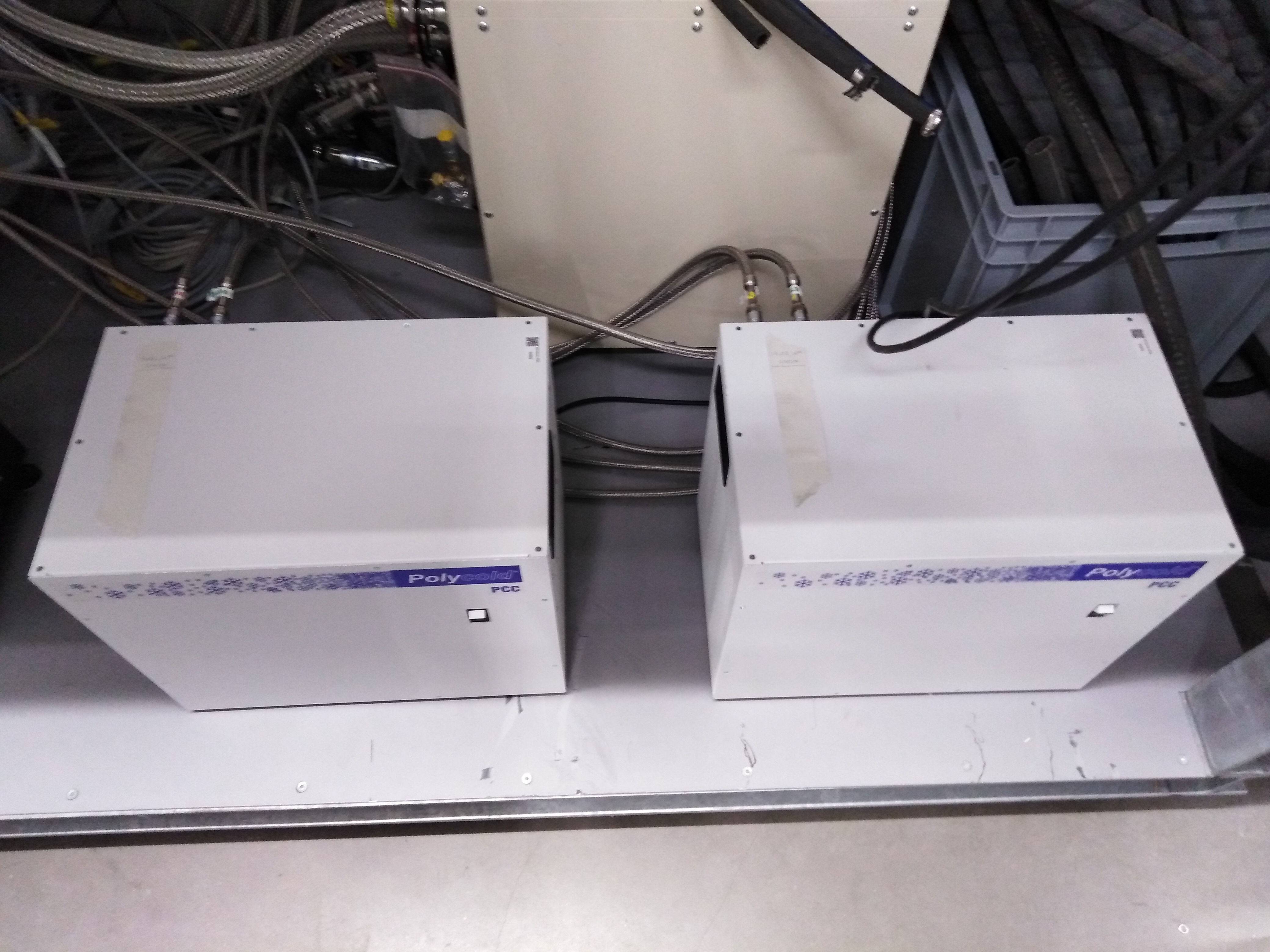
Fig. 4.14 The pnCCD chillers each consists of a cryocooler, an air-cooled compressor, and a pair of self sealing supply/return gas lines to link the cryocooler to the associated compressor.
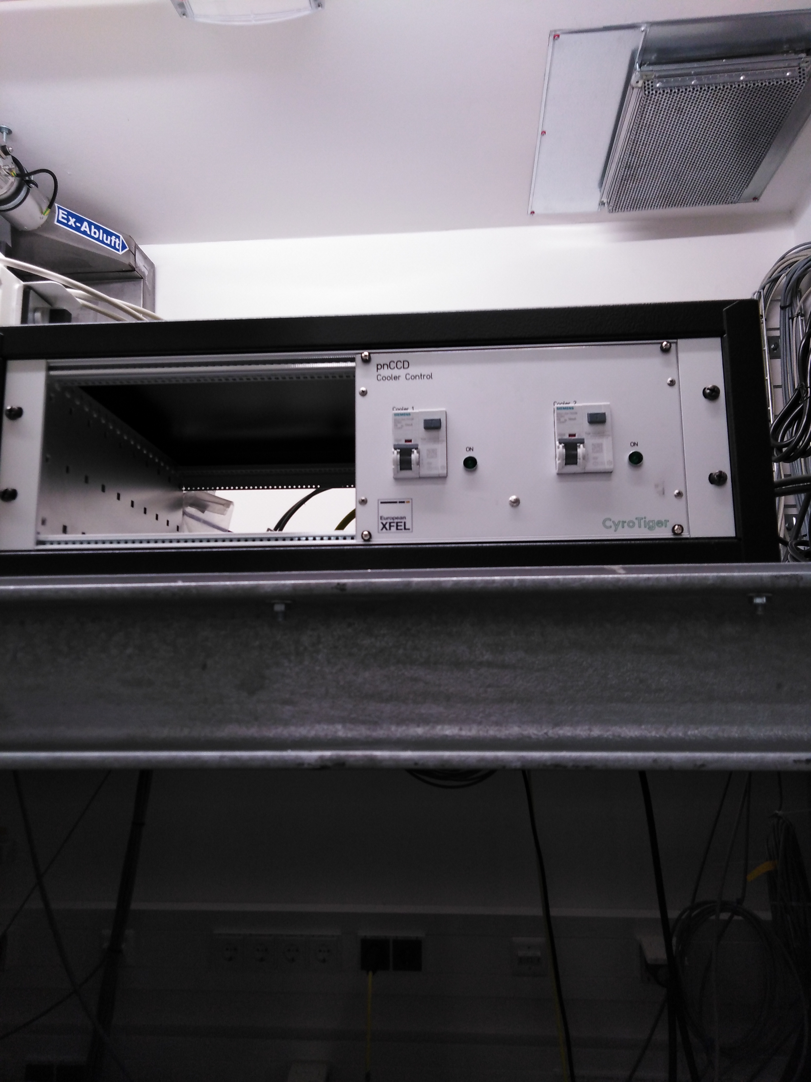
Fig. 4.15 Each of the pnCCD chillers has a cooler control unit shown here.
4.9.1. Lake Shore Temperature Controller
The temperature of the pnCCD detector is stabilized by two boralectric heaters installed next to the CCD plane (one heater per each detector module). A PT-100 temperature sensor is installed on the same support for each heater. An additional 100-W heating cartridge is installed near the tip of a copper rod, acting as the cold head, close to each sensor module. A PT-100 is also installed there per cold head’s heater. These cold head heaters are sometimes required to counterbalance the cooling power provided by the Chillers. They are normally OFF and may be carefully turned ON when needed. The Lake Shore 336 unit monitors the status of the boralectric heaters and the PCC coolers; reads the PT-100 temperature sensors; and controls the heaters by powering them in a closed feedback loop with the corresponding PT-100 temperature sensors in order to reach a specified temperature.
Tip
- The Lake Shore 336 has several heater settings 0: Off, 1: Low, 2: Medium, 3: High. You should only use the High setting since the other settings are very inefficient.
- The Lake Shore unit will turn off all heating loops if the CCD temperatures (for both pnCCD modules) reach their setpoints.
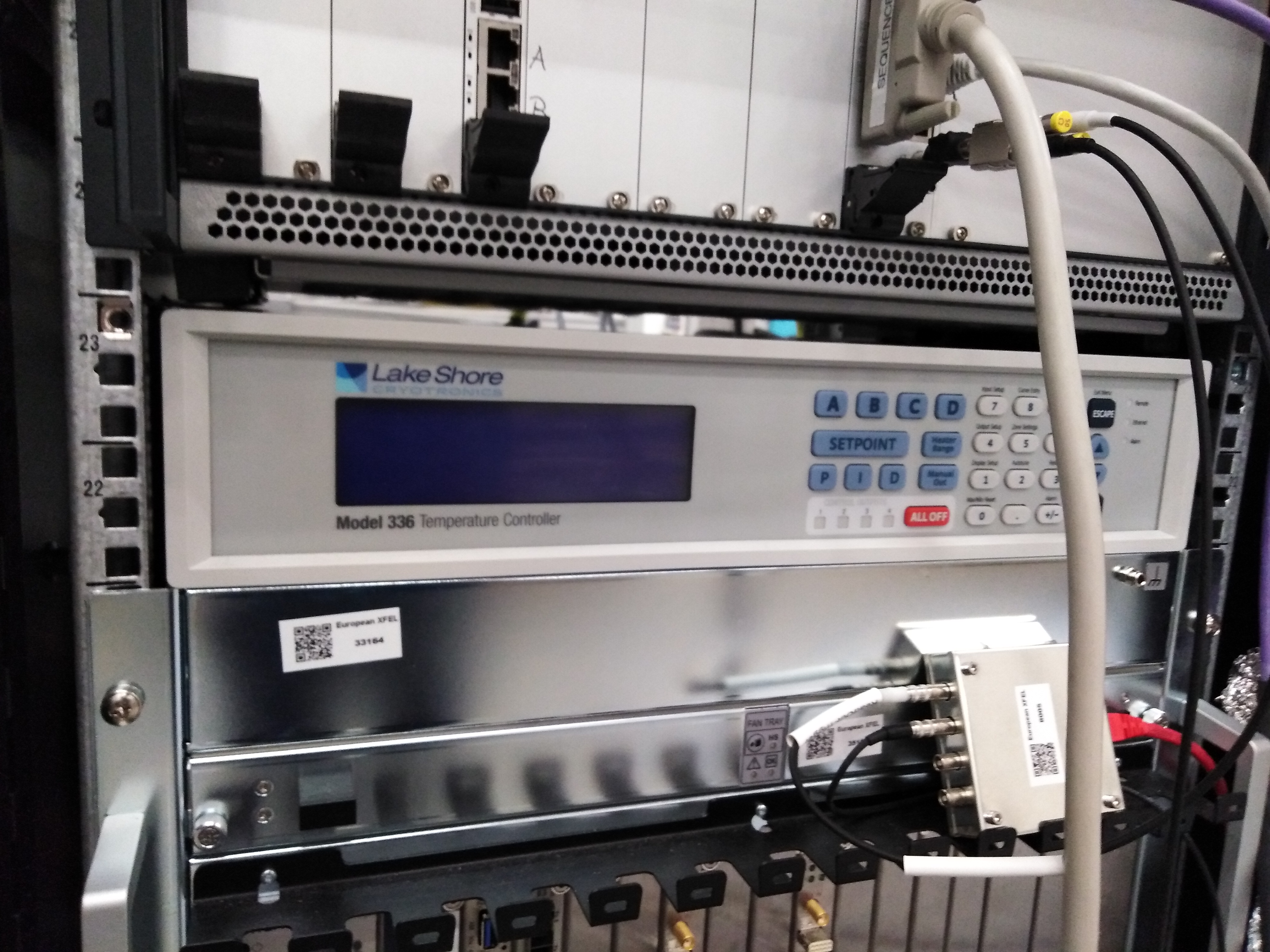
Fig. 4.16 The front of the Lake Shore 336 temperature control unit.
4.10. pnCCD Interlock System
The pnCCD is equipped with a hardware based interlock system (see Fig. 4.17), set by Nils Rennhack (European XFEL employee), which protects the detector from dangerous operating conditions such as a vacuum accident or a risky physical motion of the sensor. The interlock system relies on the successful operation of a Maxigauge (see Fig. 4.18) connected to the full range pressure gauge (\(P_{CCD, high}\)) on top of the pnCCD chamber (see Fig. 4.12 and Fig. 5.21). This Maxigauge is not controlled by Karabo and needs to be set manually.
Moreover, the MPOD system as well as the cooling system are also interlocked to prevent the detector from being biased when the vacuum in the system is bad and to prevent operating the detector when it is not cooled, respectively.
The interlock becomes active once the vacuum in the pnCCD chamber goes below the low pressure setpoint for the relay of channel 2 on the Maxigauge (currently set to \(10^{-5}\) mbar). If the interlock is broken (for example, by a pressure rise above the high pressure setpoint of the aforementioned relay, which is currently set to \(10^{-4}\) mbar), the \(V_{2}\) valve will be closed and the MPOD and the cooling systems will be interlocked. The vacuum interlock is triggered if:
- The full range pressure gauge (\(P_{CCD, high}\)) on top of the pnCCD chamber (see Fig. 4.12 and Fig. 5.21) is reading a value outside the nominal operating range or if it does not provide a proper signal. The nominal operating range for this pressure gauge can be set by the SQS beamline scientists. Currently, the desired setpoints are \(10^{-5}\) mbar (low pressure) and \(10^{-4}\) mbar (high pressure). These pressure setpoints need to be changed/set manually for the relay of channel 2 on the Maxigauge. The interlock will not function properly if you use a different channel on the Maxigauge.
- One of the two turbo pumps on the pnCCD vessel (\(TP_{1}\) or \(TP_{2}\) on Fig. 4.12, also see Fig. 5.18) or the scroll pump (
SQS For. lineon Fig. 4.12, also see Fig. 5.19) fails, i.e., if the power is OFF or if the turbo pump is not running at its full acceleration speed.- The pressure switch \(P_{CompAir}\) changes its state to below the threshold.
- Valves \(V_{3}\) and \(VT_{1}\) (see Fig. 4.12) are not in their nominal positions, if the reading of their positions is impossible, or if these valves are changing position.
The MPOD will be interlocked if:
- The \(+5V\) signal acting as a
crate_enablesignal (seeMPOD) turns off the MPOD in case the relay of channel 2 of the Maxigauge is not enabled. This relay has to be enabled manually on the Maxigauge.
Without the interlock enabled, one cannot turn on the top and bottom pnCCD chillers. If you want to be allowed to turn them ON, make sure the interlock is set and is working properly.
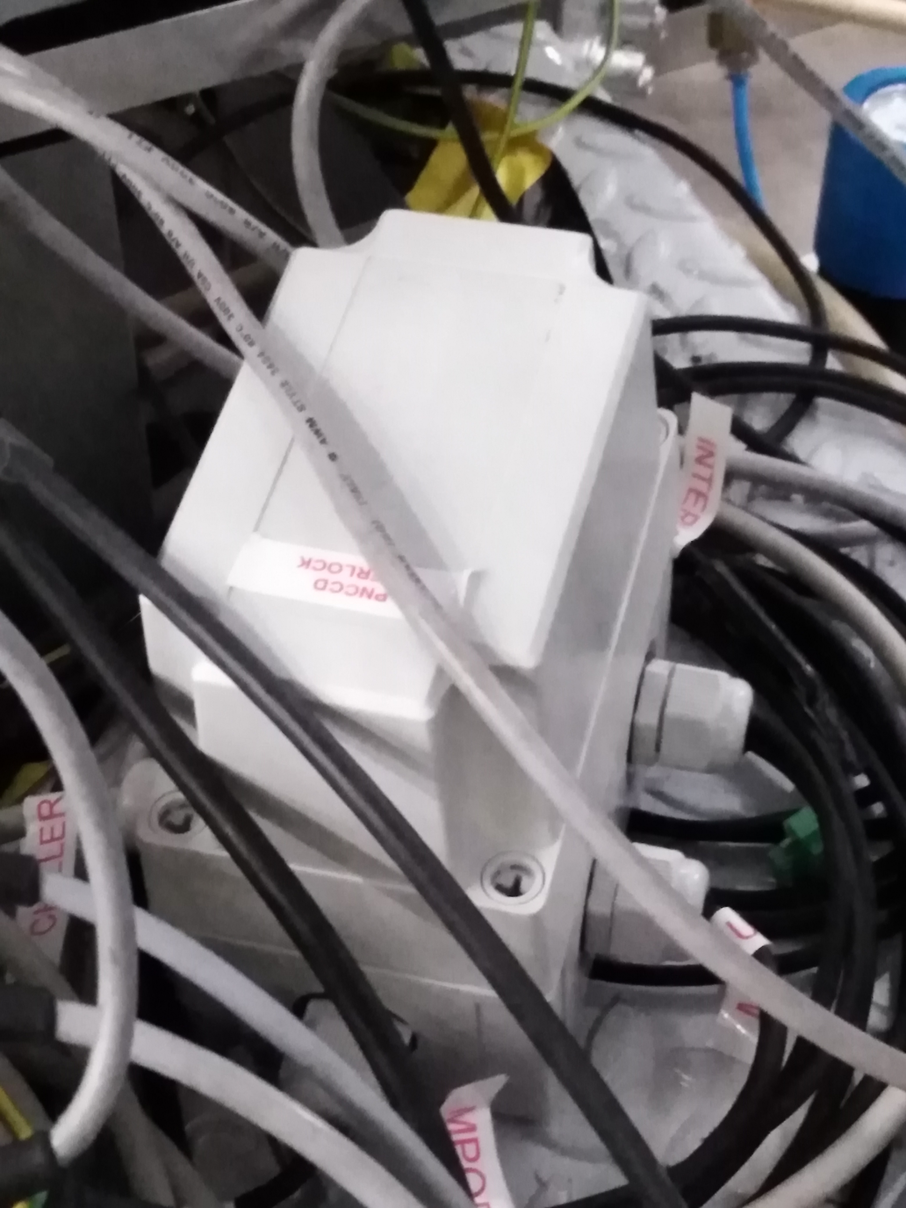
Fig. 4.17 The pnCCD interlock box.
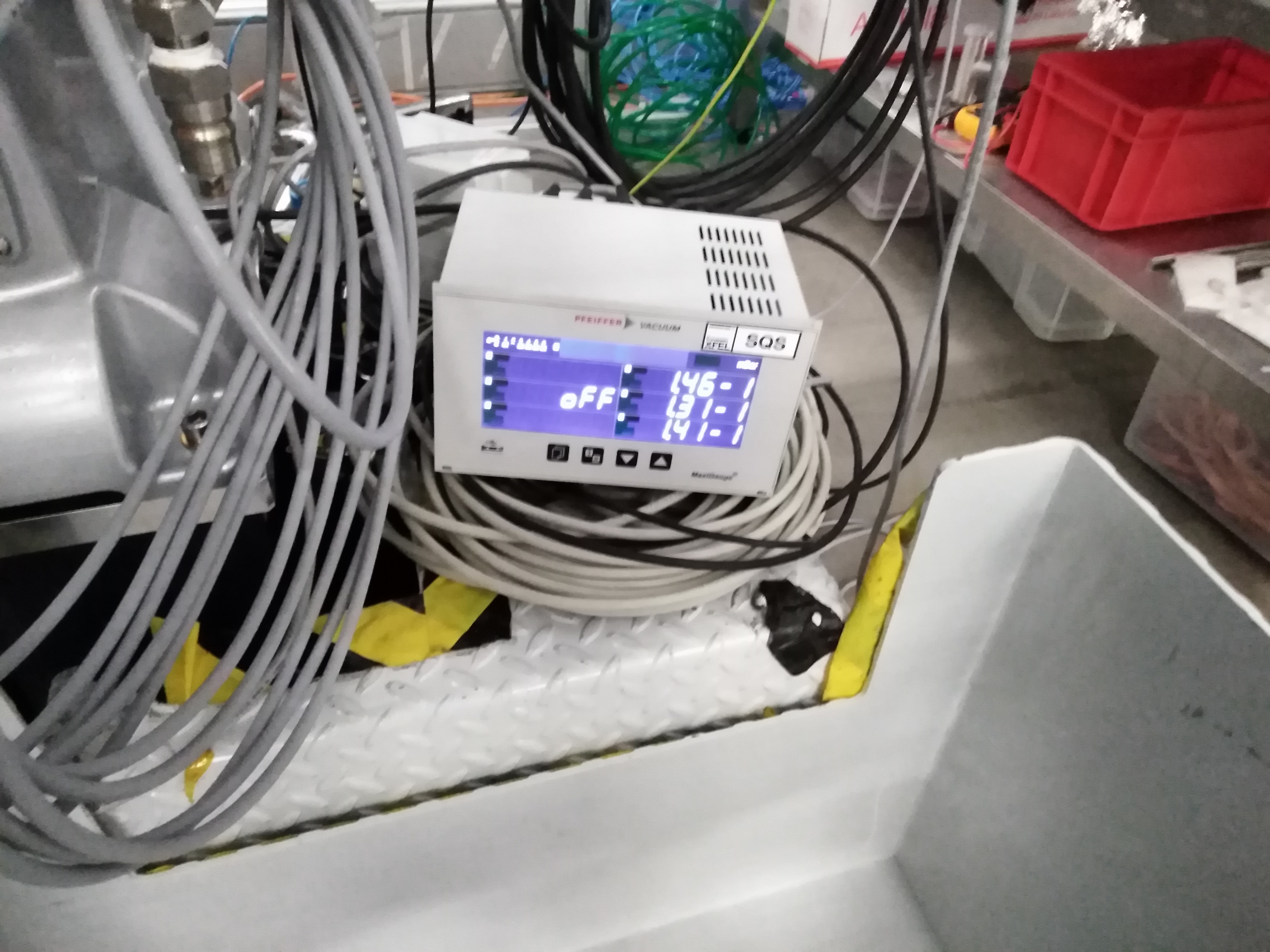
Fig. 4.18 The pnCCD Maxigauge which together with the interlock box provide the interlock to the pnCCD MPOD, vacuum system and chillers.
4.11. pnCCD Motion System
A schematic overview of the in-vacuum motion system and the pnCCD assembly are shown in Fig. 4.19. The system is UHV compatible and allows:
- positioning of the pnCCD focal plane relative to the sample environment by 300 mm in \(+z\) and \(-z\) direction.
- positioning the two focal plane modules (top and bottom CCDs) independently through coordinated motion of both focal plane halves, forming a slit like gap of a size between 0.1 mm and 40 mm for beam passage.
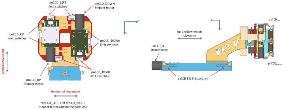
Fig. 4.19 Left: Front view of the in-vacuum focal plane detector showing the upper and lower sensors, the mechanical support and front-end electronics. Viewing direction is downstream with the FEL beam. Right: Side view of the focal plane modules, showing the in-vacuum motion system, front-end electronics components and the pnCCD detector modules. The FEL beam is hitting the focal plane modules from the right and leaves the detector on the left in downstream direction.
The motion system is based on a 5-axes UHV dry positioning system from Vacuum FAB [4] with Phytron [5] stepper motors and Renishaw [6] absolute encoders. Stepper motors, end switches, and encoders are controlled by a Beckhoff-based PLC system (see PLC). Fig. 4.20 and Fig. 4.21 show the connector specification and detailed pin definition of the feedthrough of the pnCCD motion system’s vacuum flange for the stepper motors and encoders, respectively.
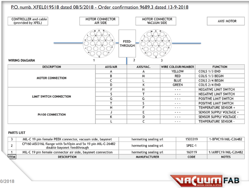
Fig. 4.20 The connector specification and detailed pin definition of the feedthrough of the pnCCD motion system’s vacuum flange for the stepper motors.
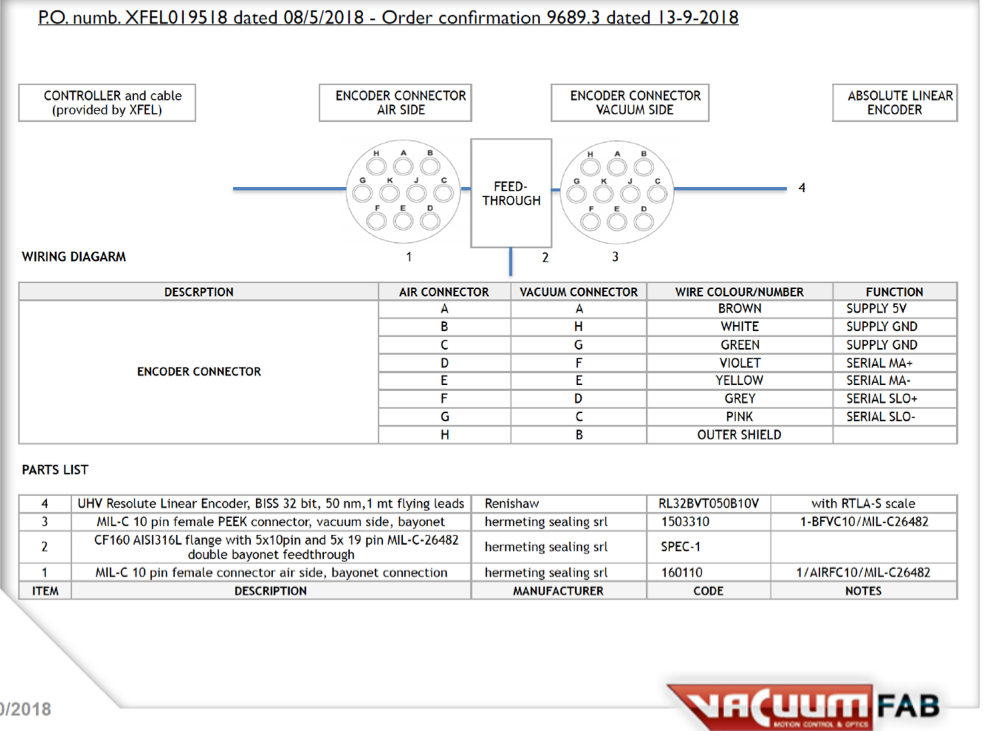
Fig. 4.21 The connector specification and detailed pin definition of the feedthrough of the pnCCD motion system’s vacuum flange for the encoders.
The vertical motion of the detector can only be achieved for one hemisphere at the time. If the encoder for vertical position of one hemisphere is reading a value above 0.1 mm, the vertical motion of the other hemisphere should be stopped and is prohibited. In addition, once the end of a limit switch for the motion of a detector’s half along an axis is reached, the system will stop that motion. Furthermore, motion of the detector in up- and downstream directions is only possible if the upstream gate valve (Valve \(V_{1}\) on Fig. 4.12) is open.
The detector’s motion interlock is triggered and will immediately stop and disable all stepper motors if:
- an end of a limit switch is reached.
- the collision switch is activated.
- the readings of position encoder values are not proper.
- the position encoders are not powered.
If the position encoders are powered and are reading proper values, motion toward a direction opposed to the collision switch direction is allowed for a maximum space of 2 mm at reduced speed (\(10 \%\)).
The SQS beamline scientists are responsible for and operate the pnCCD motion system.
Footnotes
| [1] | PNSensor GmbH, Otto-Hahn-Ring 6, 81739 München, Germany. |
| [2] | http://www.wiener-d.com/ |
| [3] | tectra GmbH, Reuterweg 51 – 53, 60323 Frankfurt/M, Germany. |
| [4] | http://www.vacuumfab.it/index.php/en/ |
| [5] | Phytron GmbH, Industriestr. 12, 82194 Gröbenzell, Germany (https://www.phytron.eu). |
| [6] | https://www.renishaw.com/ |