5. The Hardware Setup and Cable Connections
In this chapter, the pnCCD hardware setup and cable connections are explained for each individual system related to the detector. See HardwareChapter for details about the pnCCD hardware systems.
5.1. In-Vacuum Electronics Cable Connections
Inside the pnCCD vacuum chamber, there are some very fragile and delicate cables which are related to the PT-100 temperature sensors, as well as the motion system control. None of these cables should be touched unless you are an expert and you need to repair them. Even then, make sure Yevheniy Ovcharenko (European XFEL employee) from SQS is present and is supervising you.
The pnCCD CAMEX and readout related electronics boards are all housed in a specific housing, which is permanently connected to the side of the pnCCD chamber (see Fig. 5.1). The cables that are connected to this housing are all bundled together and are:
- The MPOD cables (see Fig. 5.16), which provide power. There are two sets of these cables for the top and bottom pnCCD modules. These cables are thick blue cables with male connectors that have many pins in them. They are labelled as
CAMERA HEAD TOPandCAMERA HEAD BOTTOM,CMX TOPandCMX BOTTOM,CAMERA HEAD ELECTRONICS TOPandCAMERA HEAD ELECTRONICS BOTTOMand should be connected to theCAM HEAD TOPandCAM HEAD BOT,CMX TOPandCMX BOT,CAM E TOPandCAM E BOTinputs of the electronics housing shown in Fig. 5.1, respectively.- The sequencer cable which is a creamy color thick cable with a male connector with many pins labelled as
SEQUENCER. It should be connected to the input labelled asSEQon the housing shown in Fig. 5.1. The other side of it is connected to the sequencer module (see Fig. 5.4).- The readout cables, which are made in house by Kai-Eric Ballak (European XFEL employee). They are of darker blue color and much shorter than the MPOD cables. They have male connectrors with 8 pins on one side (labelled as
AandB) and 8 LEMO cables on the other side. There are two sets of such cables (for top and bottom pnCCD modules). These cables should be connected to the inputs labelled asAandBon the housing shown in Fig. 5.1. The LEMO cables are connected to the back of the FastADC digitizers as shown in Fig. 5.11 (also see entries 13 and 67 of the pnCCD elog).- An Ethernet cable near the input labelled as
SEQ(see Fig. 5.3). This cable is inside the bundle of cables related to the pnCCD in-vacuum electronics housing. One side of this Ethernet cable goes on the electronics housing on the side of the pnCCD chamber and the other side (with the printed label ofTo the Sequencer) should be connected to an ethernet input on the left side of the sequencer labelled asB(see Fig. 5.2).- The three LEMO inputs in the pnCCD in-vacuum housing are only for test purposes and they do not need to be attached to any cables during pnCCD normal operations. In some of the commissioning beamtimes, PNSensor representatives may need to use these inputs to test signals.
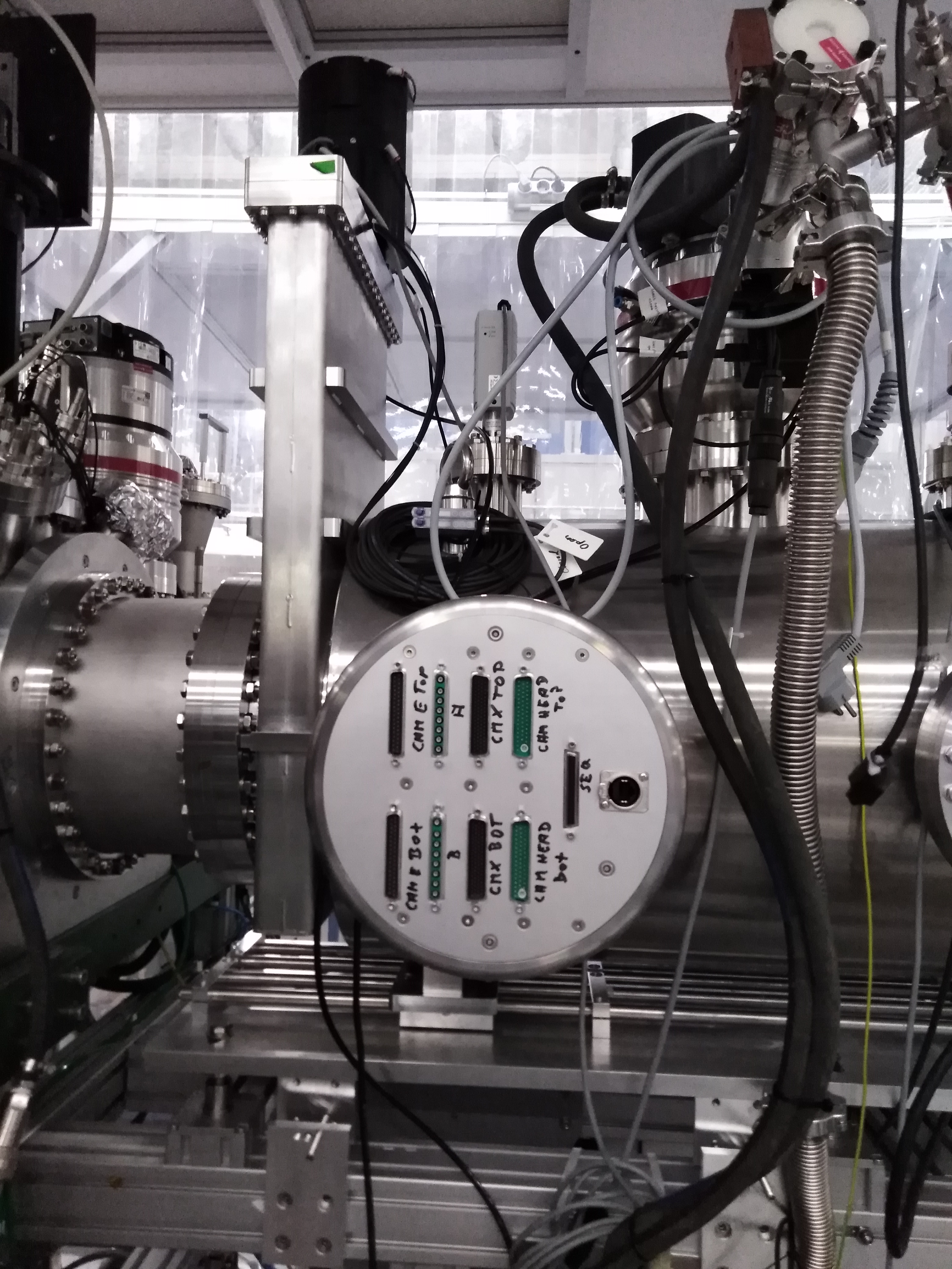
Fig. 5.1 The pnCCD CAMEX and readout related electronics boards are all housed in a specific housing shown here, which is permanently connected to the side of the pnCCD chamber. Make sure all corresponding cables are connected to the inputs with the correct label.
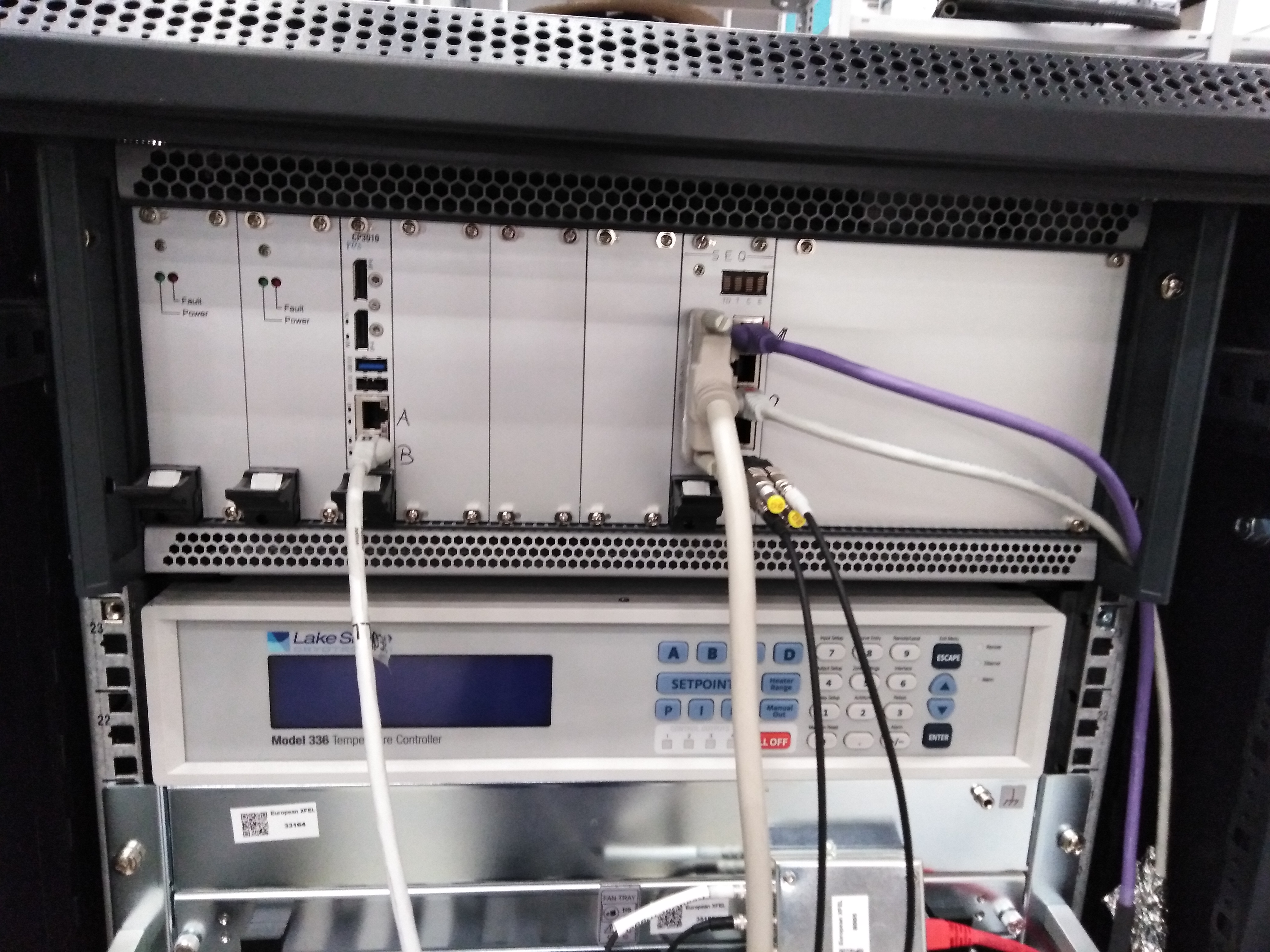
Fig. 5.2 One side of the ethernet cable that is connected to the housing of the pnCCD CAMEX and readout related electronics boards is connected to the B input of the sequencer, shown on the top left side of this figure.
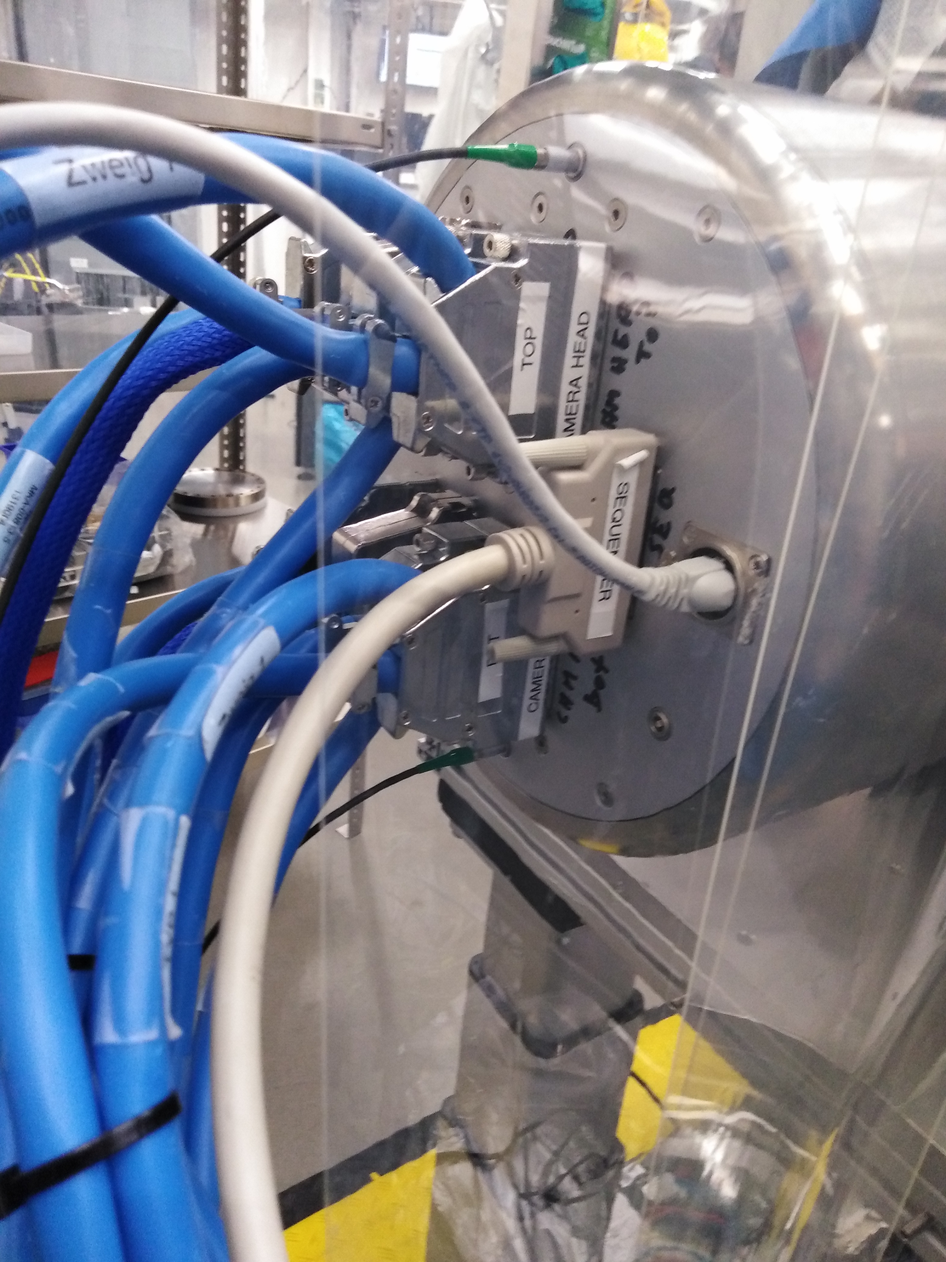
Fig. 5.3 All cables are attached to the in-vacuum electronics housing. The LEMO cables with a green tape on the top and bottom of the image do not need to be there. They were only there to test a signal. The image shows the chamber in a temporary clean tent.
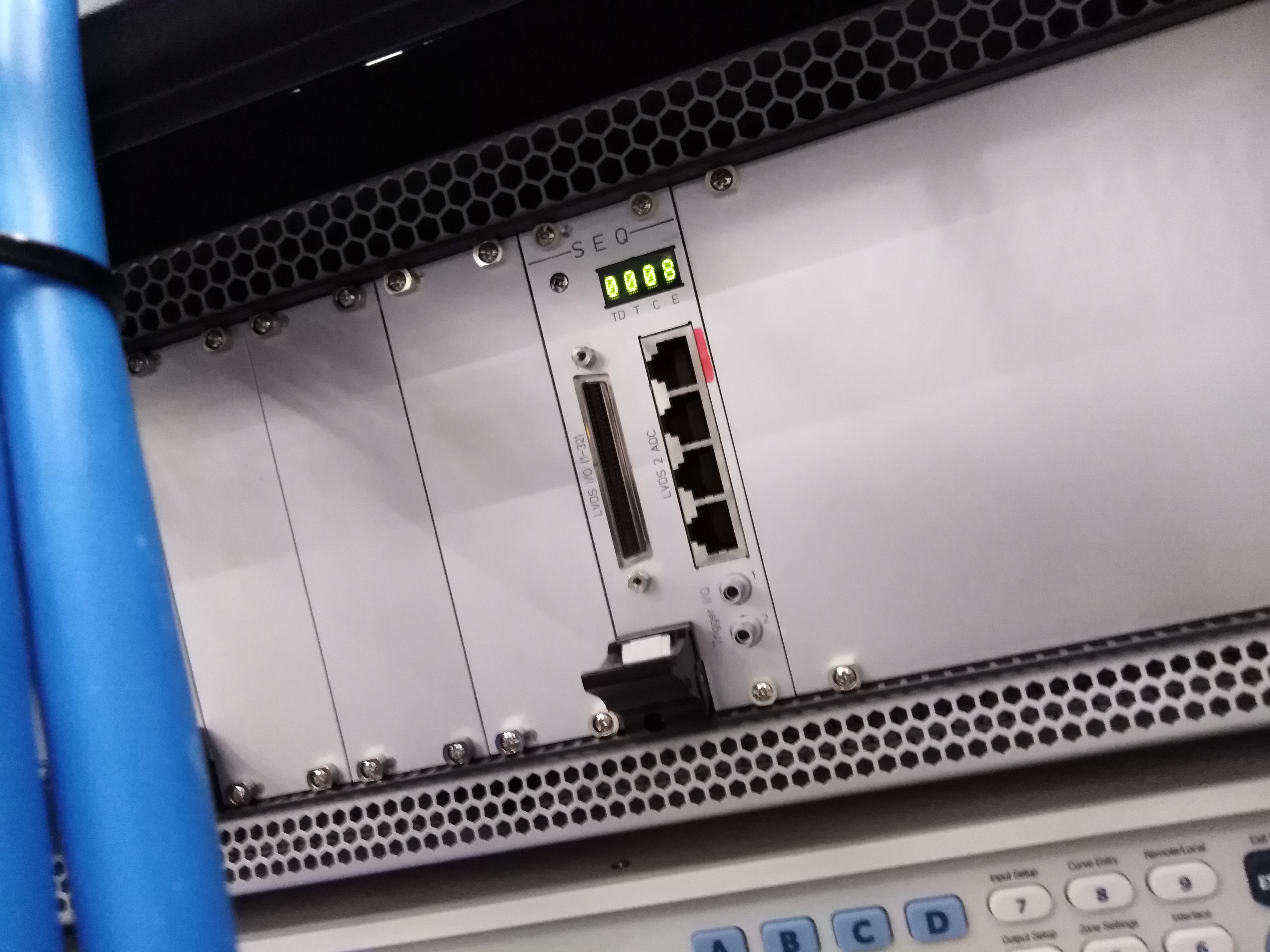
Fig. 5.4 The sequencer cable (a creamy color cable labelled as SEQUENCER) should be connected to the input labelled as SEQ on the housing shown in Fig. 5.1. The other side of it is connected to the input labelled as LVDS I/O (1-32) on the sequencer module as shown here.
5.2. Cable Connections for the Front-End Electronics Outside Vacuum
The electronics rack (see Fig. 4.6) of pnCCD has many cables associated to each module. Here, we explain those cables that may get disconnected from time to time depending on whether or not pnCCD is in use on the SQS beamline.
Warning
- Do not forget to ground the pnCCD electronics rack. This can be achieved using a cable with yellow and green stripes.
5.2.1. Data Transfer and Communication with the DAQ
The DAQ Fiber Optic cable: This cable is shown in Fig. 5.5 and Fig. 5.11. It is a 10 Gbit Fiber Optic cable which acts as a network link to the data acquisition system for data transfer. The connection is on the rear of the \(\mu\!\) TCA.4 crate (as shown in Fig. 5.11). The other side of this Fiber Optic should be connected to the SQS patch panel on the wall of the SQS hutch as shown in Fig. 5.5.
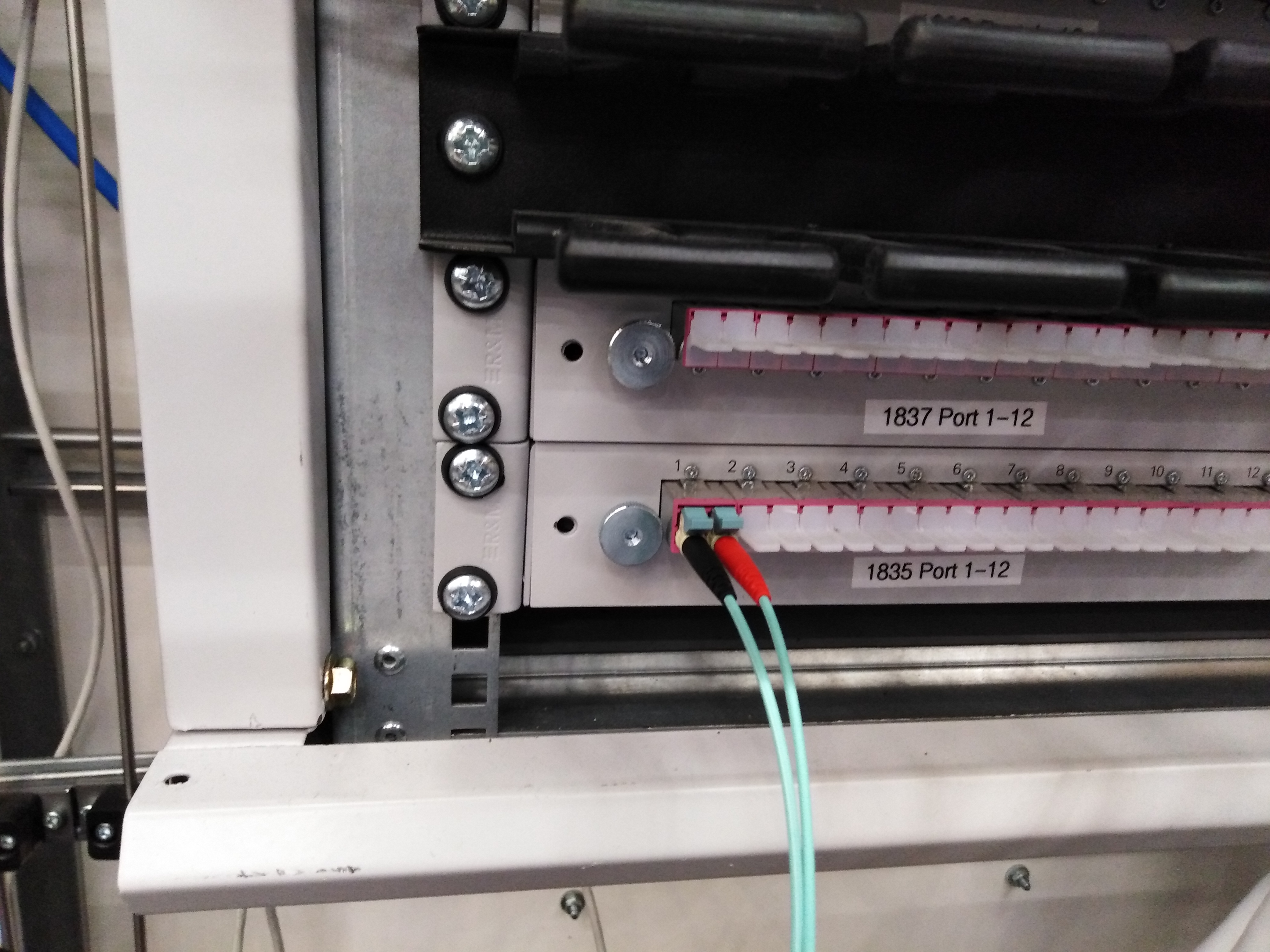
Fig. 5.5 The 10 Gbit Fiber Optic cable connected to the SQS patch panel on the wall of the SQS hutch.
5.2.2. Clock and Control
The Clock and Control cable: This cable is explained previously in clockAndControl and provides the timing triggers. This is a yellow cable, labelled as mTCA, connected to another SQS patch panel on the wall of the SQS hutch as shown in Fig. 5.6 and to the \(\mu\!\) TCA.4 crate’s timing card as shown in Fig. 5.7 and Fig. 5.8.
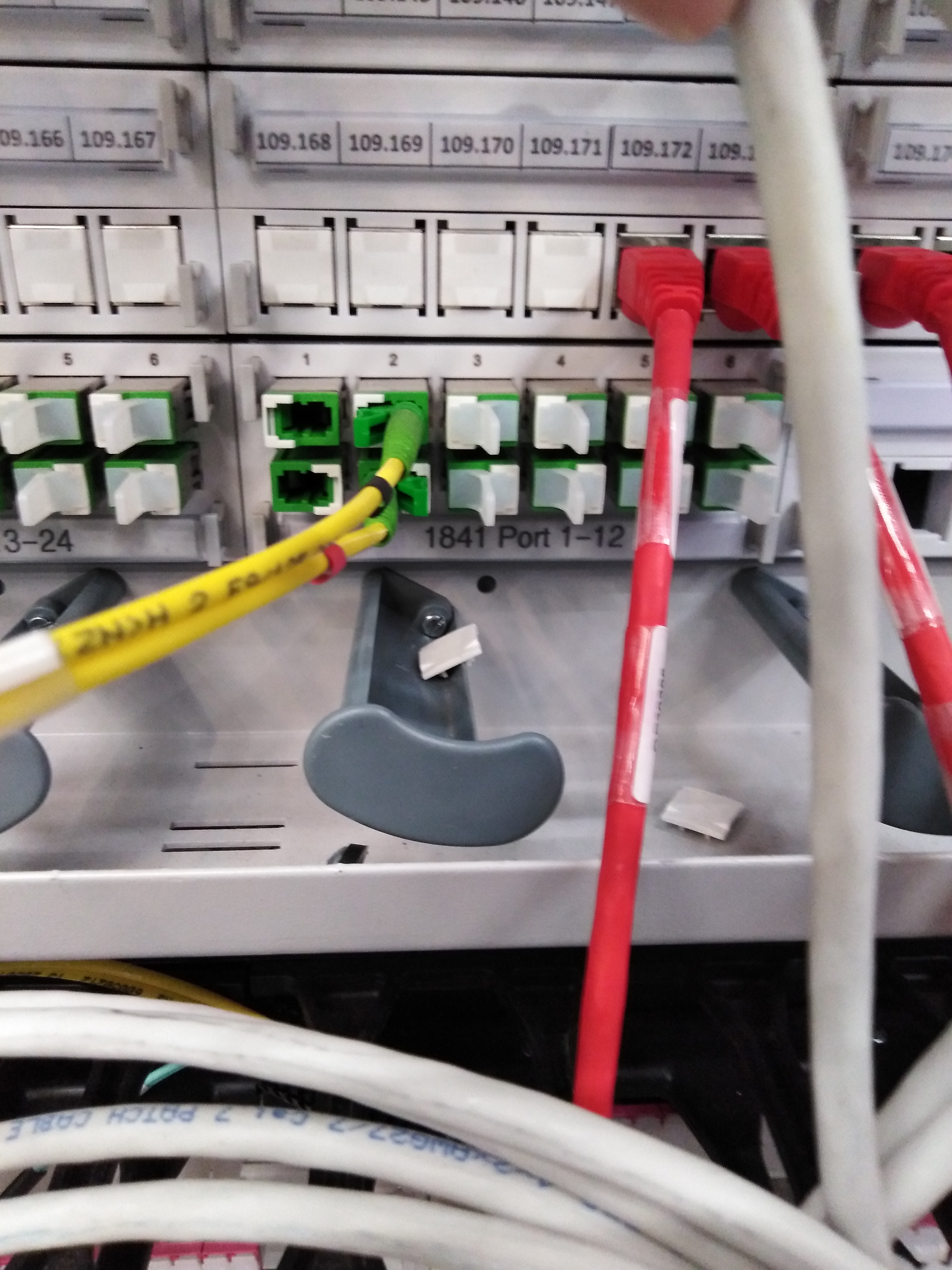
Fig. 5.6 The Clock and Control cable connected to the SQS patch panel on the wall of the SQS hutch. The yellow cable with a red tape goes to the bottom port and the yellow cable with a black tape goes to the top port.
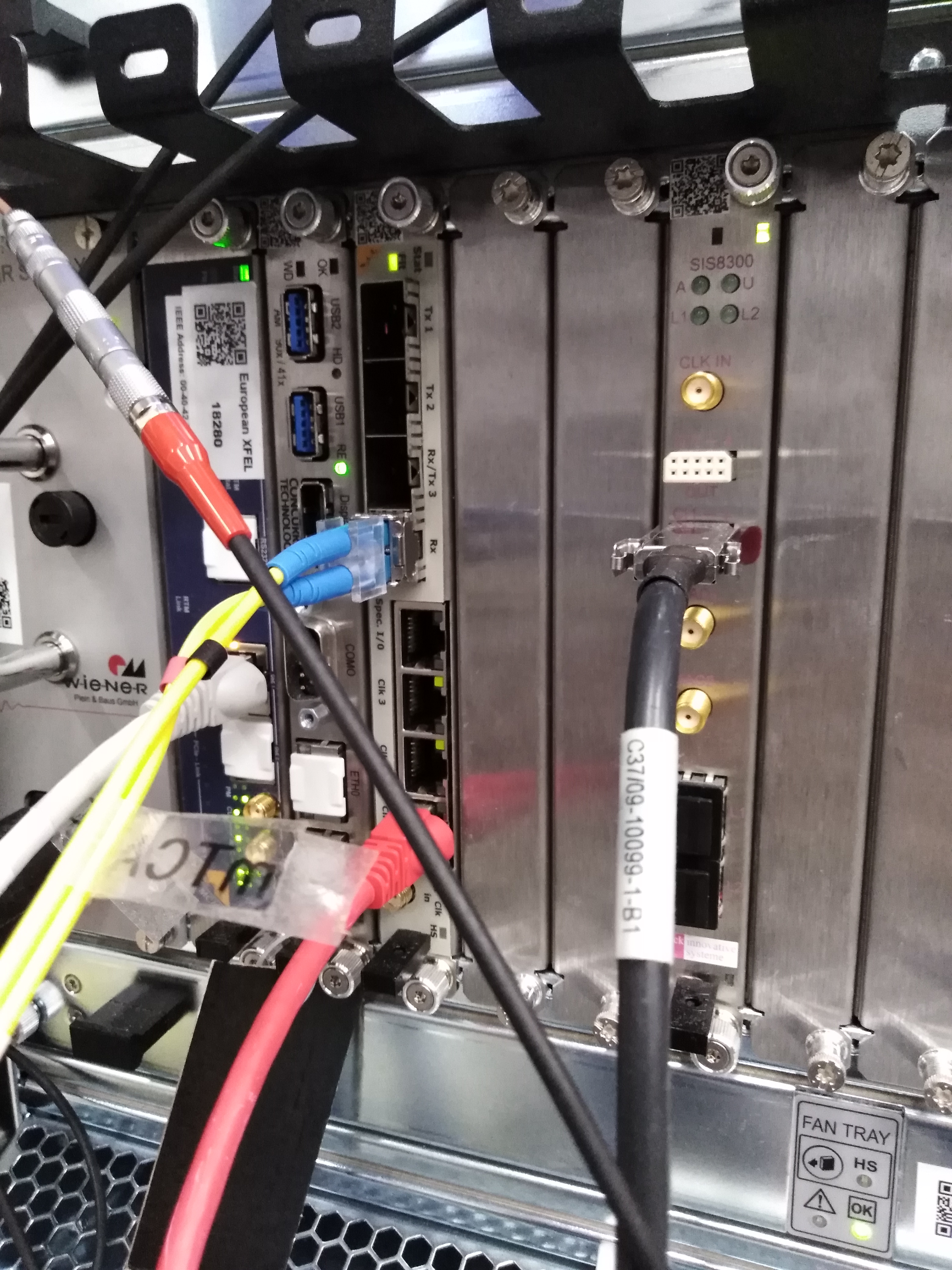
Fig. 5.7 The Clock and Control cable connected to the \(\mu\!\) TCA.4 crate’s timing card. The yellow cable with a black tape goes to the top port.
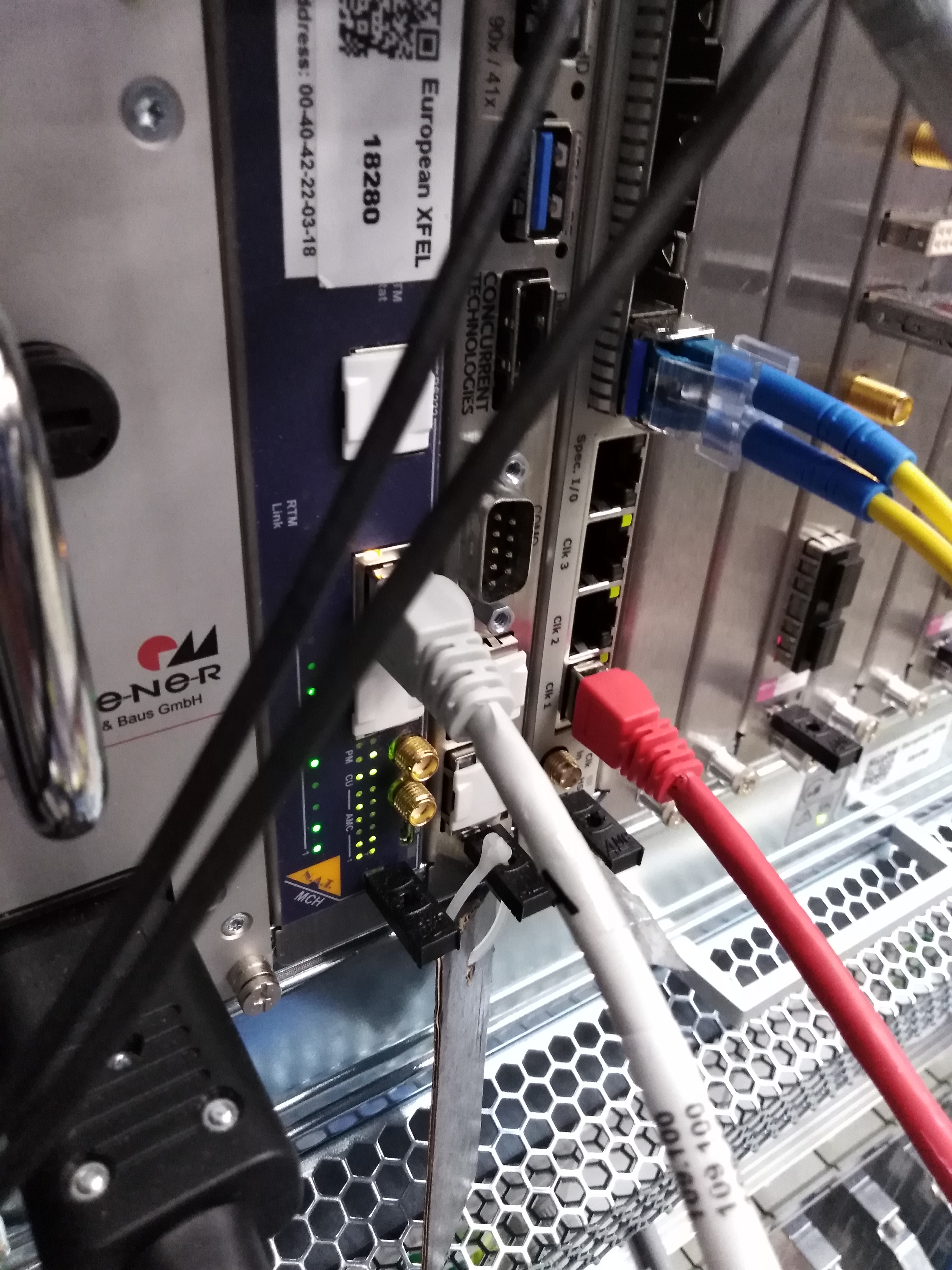
Fig. 5.8 Same as Fig. 5.7 but from a different angle. The yellow cable with a black tape goes to the top port.
5.2.3. The \(\mu\!\) TCA crate
The white Ethernet cable plugged into the \(\mu\!\) TCA Carrier Hub (MCH) card on the pnCCD \(\mu\!\) TCA.4 crate: this is a white Ethernet cable labelled as 109.100 already shown in Fig. 5.7, Fig. 5.8, and Fig. 5.9.
The \(\mu\!\) TCA.4 crate has a power cable which needs to be connected to an outlet. This can be seen in Fig. 5.10 as a thick black cable with a rectangular head at the left bottom corner of the picture connected to the power module of the \(\mu\!\) TCA.4 crate.
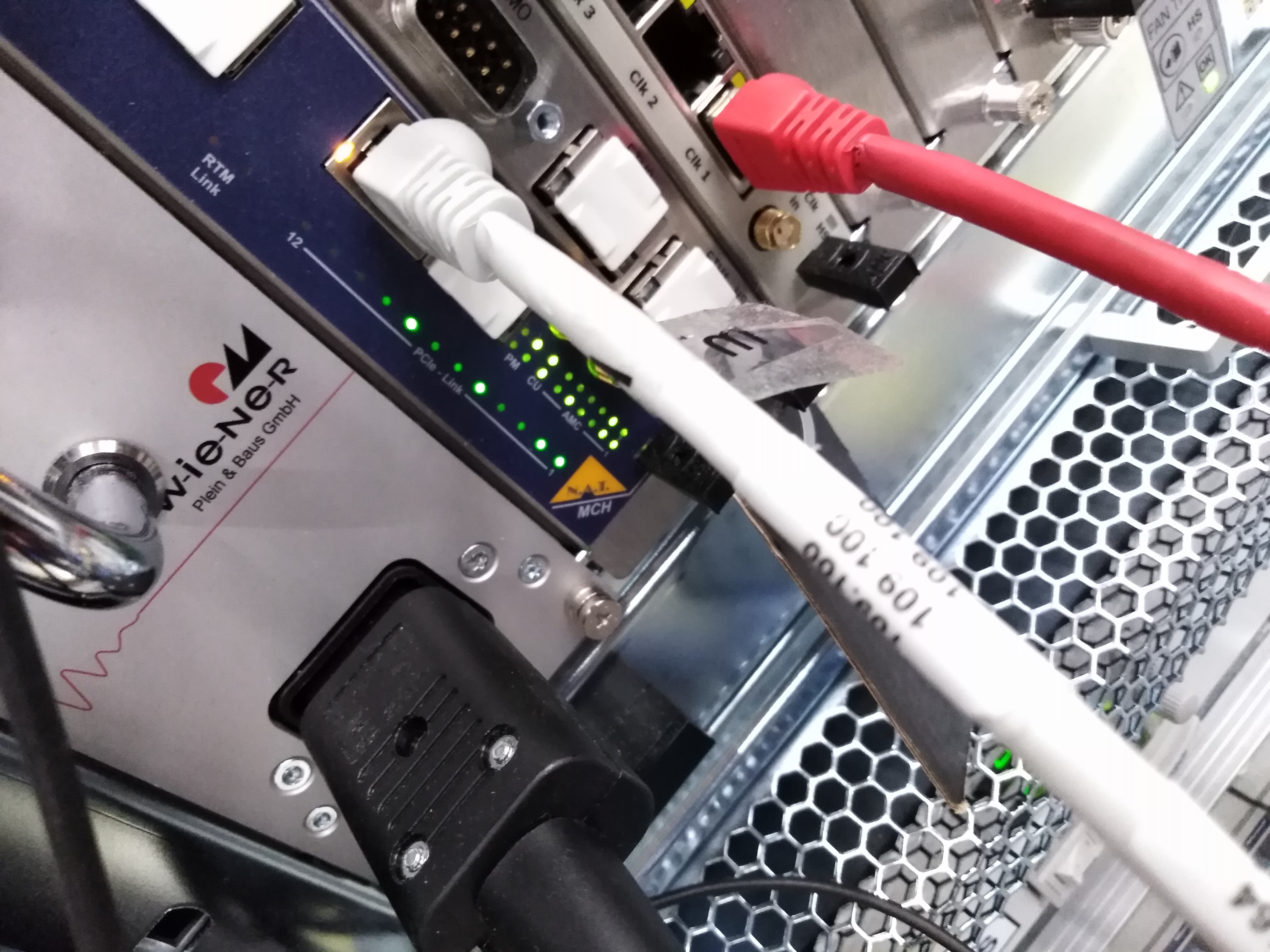
Fig. 5.9 The white Ethernet cable, labelled as 109.100, plugged into the \(\mu\!\) TCA Carrier Hub (MCH) card on the pnCCD \(\mu\!\) TCA.4 crate
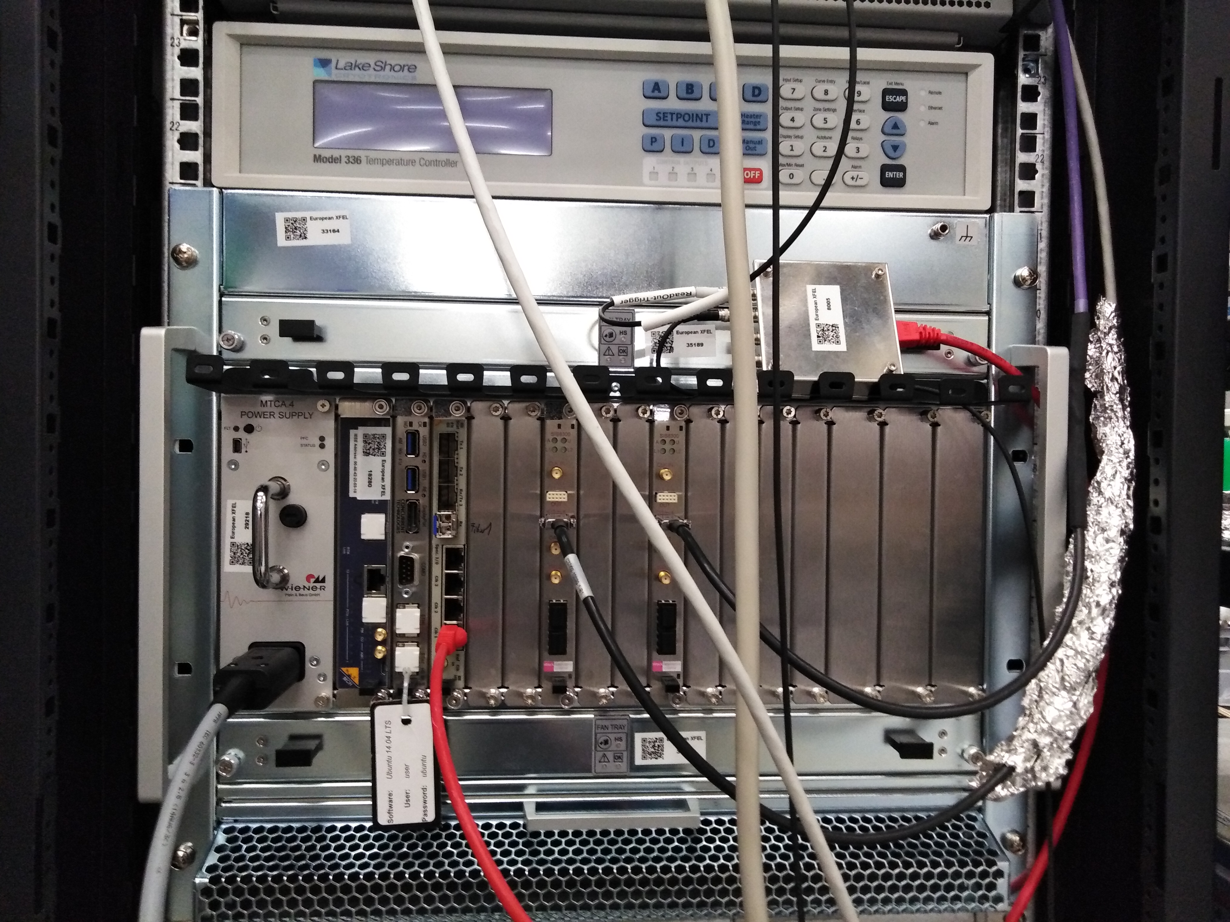
Fig. 5.10 The \(\mu\!\) TCA.4 crate needs a power cable, which is a thick black cable with a rectangular head at the left bottom corner of the picture connected to the power module of the \(\mu\!\) TCA.4 crate.
5.2.4. FastADC Digitizers
The cable connections for the FastADC digitizers are as follows:
- The two black cables shown on Fig. 4.7 are the RTM digital input cables for the two FastADCs. These cables are soldered onto two Ethernet cables that are white and purple (see Fig. 4.8). The cable constructions are made in house by Kai-Eric Ballak (European XFEL employee). The RTM sides are connected to the ADCs as shows on Fig. 4.7, while the Ethernet sides of these two cables are connected to the Ethernet inputs 1 and 3 on the right hand side of the sequencer module (physical input 1 is labelled as 1 but physical input 3 is for some reason labelled as 2 as shown on Fig. 4.8). Please see the following warning message at the end of this subsection.
- The RTM digital input cable with a red mark on it is connected to ADC1 (FastADC of the top pnCCD sensor). It is soldered to the white Ethernet cable, which, in turn, is connected to the third physical Ethernet input on the right side of the sequencer. This latter input is labelled 2 by a pen. Please keep this cable as is and do not swap it with the other one. This is so that the noise levels corresponding to the associated FastADC can be always compared to those measured previously.
- Similarly, the other unmarked RTM digital input cable is connected to ADC2 (FastADC of the bottom pnCCD sensor). It is soldered to the purple Ethernet cable, which, in turn, is connected to the first physical Ethernet input on the right side of the sequencer on the very top. This latter input is labelled 1 by a pen. Please keep this cable as is and do not swap it with the other one. This is so that the noise levels corresponding to the associated FastADC can be always compared to those measured previously.
- There are 10 LEMO cables connected to
ADC2(for the bottom pnCCD module) and 6 LEMO cables connected toADC1(for the top pnCCD module). These 16 LEMO cables carry signals from the 16 CAMEX readouts (8 per pnCCD sensor). The LEMO cables merge into the two cables that are connected to the readout boardsAandBon the in-vacuum electronics housing (see Fig. 5.1).
Warning
- There are two more Ethernet inputs on the right side of the sequencer (physical inputs 2 and 4), which are noisy. Please avoid connecting the white and purple Ethernet cables that are connected to the RTM digital cables to inputs 2 and 4 of the sequencer. Also, please do not remove the aluminium foil around these cables and avoid touching them. The foil is there to reduce the noise, as these cables could be noisy. It may be that they suffer from weak soldering joints where the RTM cables meet the Ethernet cables, and thus, moving these cables may introduce a lot of unwanted noise on the FastADCs, which may interfere with the experimental data.
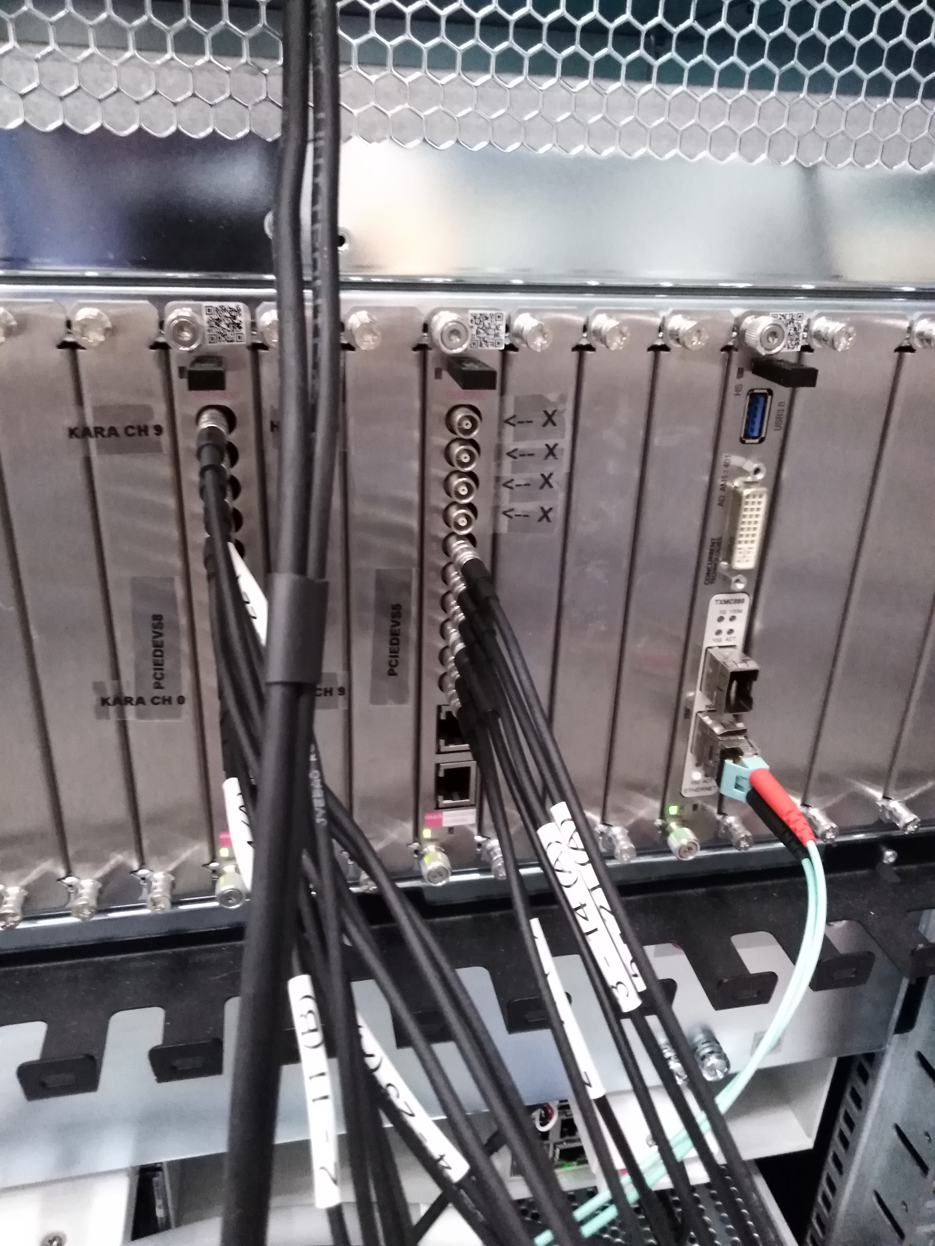
Fig. 5.11 The back panel of the two pnCCD FastADC digitizers with the LEMO cables (also see entries 13 and 67 of the pnCCD elog). These LEMO cables carry the readout signals from the top and bottom CCD modules of the pnCCD detector.
5.2.5. Sequencer
The sequencer has to have:
two Ethernet cables connected to the right hand side Ethernet inputs. These are the Ethernet cables connected to the FactADCs through the RTM cables (see
ADCCablesExplained).two Ethernet cables connected to the left hand side Ethernet inputs. These inputs on the sequencer’s left hand side are labelled as
AandB:
- The input labelled as
Ashould be connected to an Ethernet cable shown in Fig. 5.12. This latter cable is labelled as 109.098 and QR37379-2. The other side of this cable should be attached to the SQS patch panel on the wall with the same label.- The input labelled as
Bshould be connected to an Ethernet cable labelled asSEQ BOTTOM, whose other side is connected to the in-vacuum electronics housing on the side of the pnCCD chamber (seeinVacuumCableConnection).
- two LEMO cables which carry the SEQUENCER CLEAR TRIGGER and SEQUENCER START TRIGGER signals (see
clockAndControl). These should be connected to theTrigger I/O 1input (see Fig. 5.4) on the right hand side of the sequencer. However, this input is a TTL input and a LEMO cable cannot be attached to it without an adapter. Such an adapter has been made by PNSensor and it is already attached to this input. This adapter is a small peice of equipement with a black tape around it, and you can only see two LEMO T adapters. This is because each TTL input signal must be terminated by a 50 Ohm LEMO terminator in order to avoid having jitter on the siganl due to impedance mismatch. Thus, each of the two LEMO cables carrying the SEQUENCER CLEAR TRIGGER and SEQUENCER START TRIGGER signals are terminated with a 50-Ohm LEMO terminator as seen in Fig. 5.13. The LEMO cable with a white tape around it (see Fig. 5.14) carries the SEQUENCER START TRIGGER signal and needs to be connected to the top of the right LEMO T, which is attached to theTrigger I/O 1input of the sequencer (see Fig. 5.13). The other side of this LEMO cable (labelled asReadout Trigger) should go to the top left side of the trigger box (see Fig. 5.14). The LEMO cable with no tape around it and no labels (see Fig. 5.14) carries the SEQUENCER CLEAR TRIGGER signal and needs to be connected to the bottom of the left LEMO T connected to theTrigger I/O 1input of the sequencer (see Fig. 5.13). The other side of this LEMO cable should go to the second input from the top on the left side of the trigger box (see Fig. 5.14). Finally, a red Ethernet cable (see Fig. 5.15) is connected to the right side of the trigger box (see Fig. 5.14) and the other side of this red Ethernet cable should be connected to theCIK 1input on the bottom of timing card of the pnCCD \(\mu\!\) TCA.4 crate (see Fig. 5.15). The yellowClock and Controlcable (Fig. 5.7, Fig. 5.8, and Fig. 5.9) is also connected to this board. Therefore, theClock and Controlsignal is transferred into the sequencer using the red Ethernet cable and the trigger box.- a special cable with many pins which is explained in Fig. 5.4.
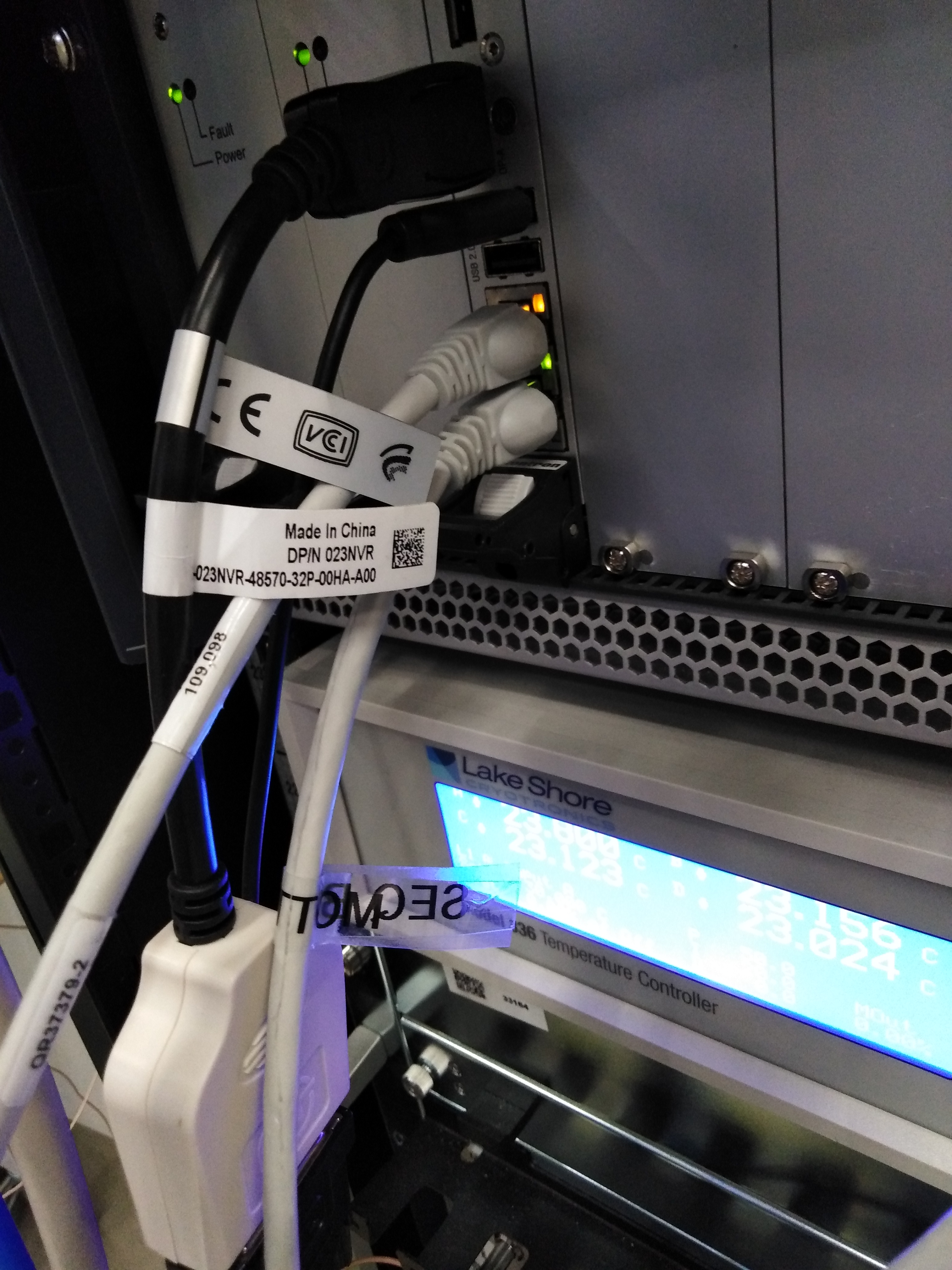
Fig. 5.12 The Ethernet cables connected to the left hand side of the sequencer. Ignore the two black cables. They were connected to some test devices during commissioning of the pnCCD detector.
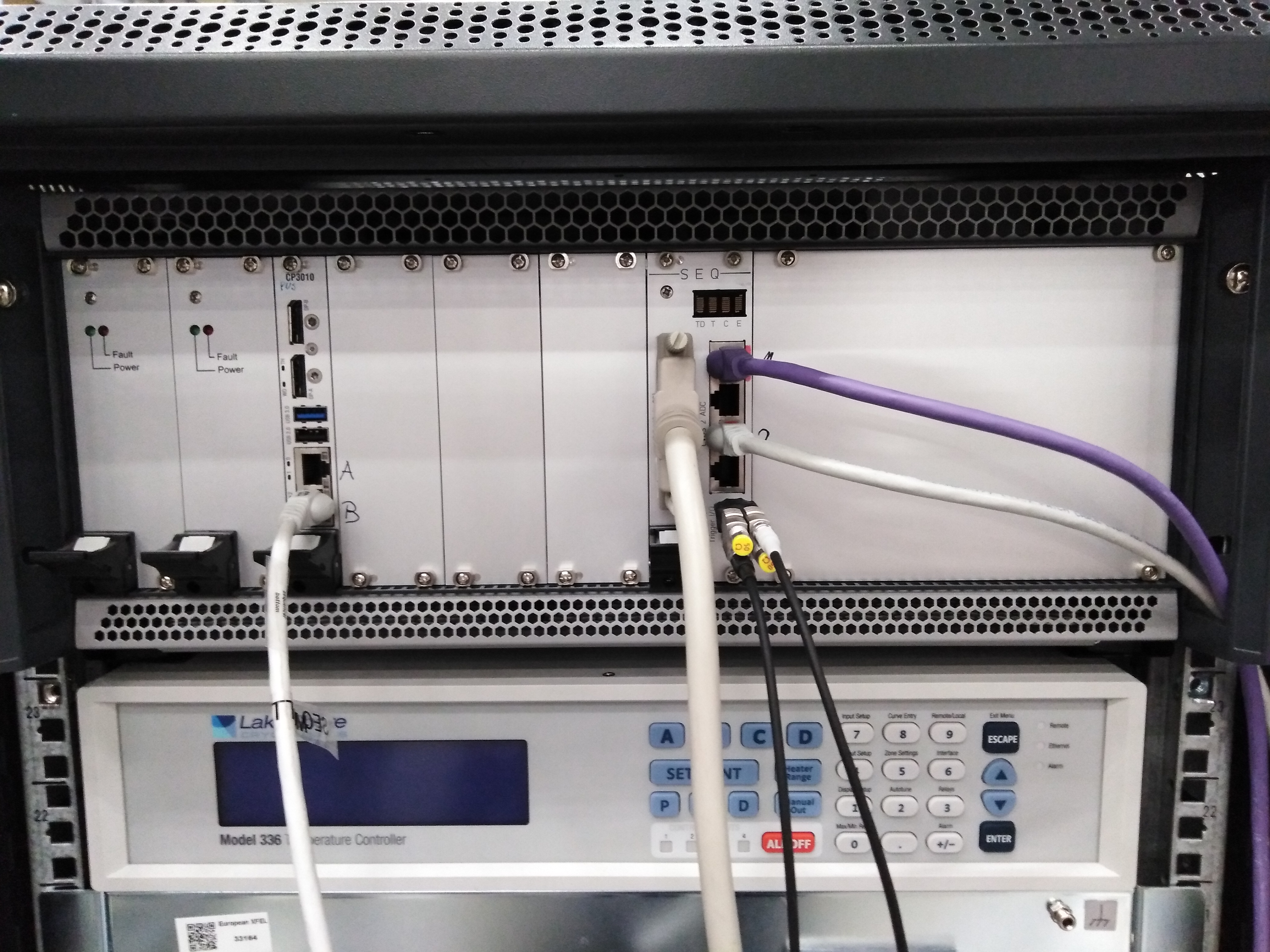
Fig. 5.13 The SEQUENCER CLEAR TRIGGER and SEQUENCER START TRIGGER signals are sent to the sequencer using the LEMO T adapters shown here on the right hand side.
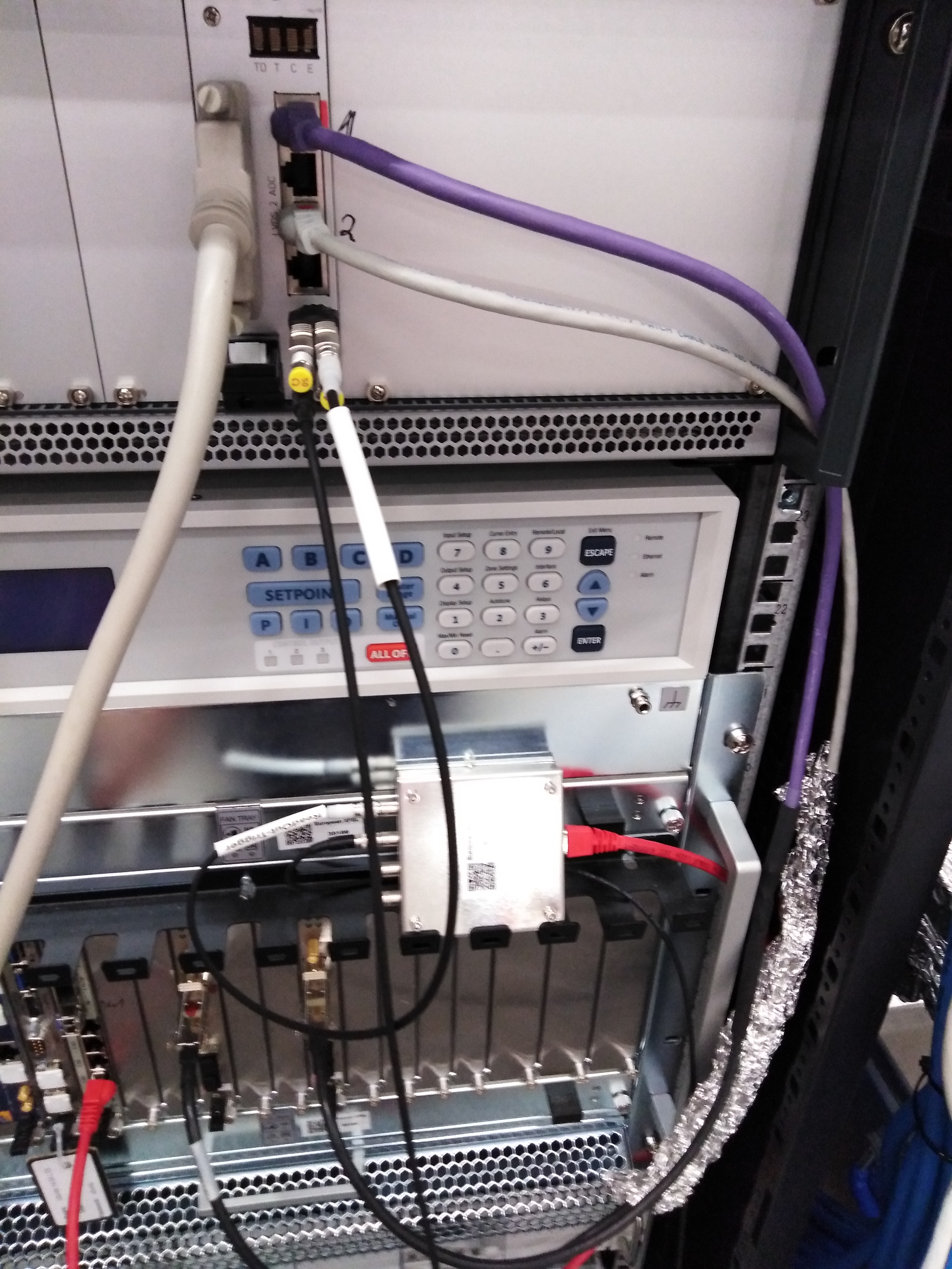
Fig. 5.14 The small box in the image separates the Clock and Control signal carried by the red Ethernet cable into the SEQUENCER CLEAR TRIGGER and SEQUENCER START TRIGGER signals carried by the two LEMO cables. The LEMO cable labelled as the Readout Trigger carries the SEQUENCER START TRIGGER signal.
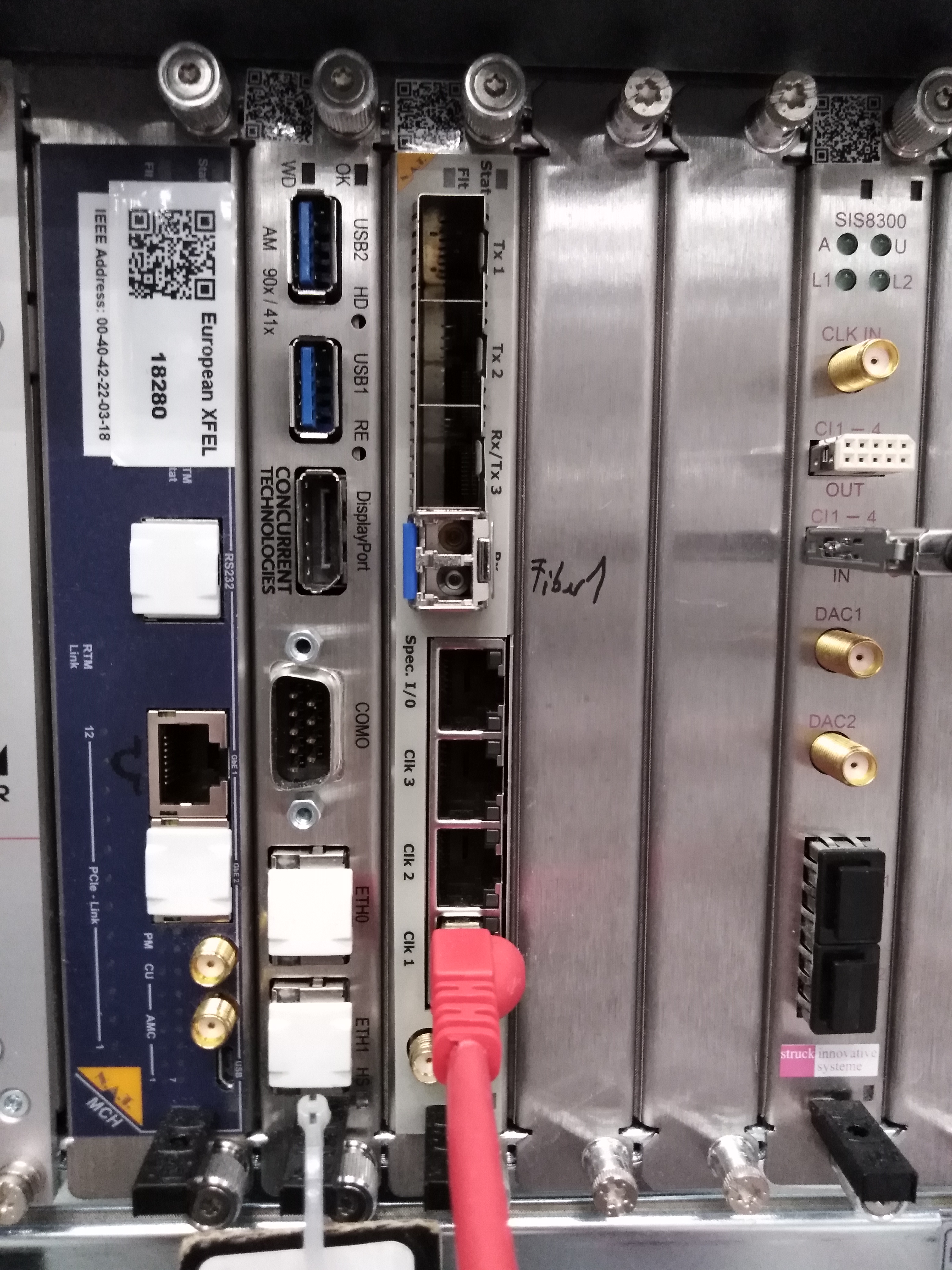
Fig. 5.15 The red Ethernet cable is connected to the timing card of the \(\mu\!\) TCA.4 crate, similar to the yellow Clock and Control cable (see Fig. 5.9).
5.3. Cable Connections for the MPOD System
The MPOD cables are already plugged into the MPOD crate (see Fig. 4.9). The other side of these cables (see Fig. 5.16) should be plugged into the in-vacuum electronics housing of the pnCCD as discussed previously in inVacuumCableConnection. The MPOD crate has to be grounded. Make sure the grounding cable (yellow/green) is correctly grounded. Finally, there is a D9 cable connected to the pnCCD interlock box (see Interlock), which needs to be plugged into the D9 input on the bottom of the MPOD crate (on the front side and to the left of the Iseg HV power supply).
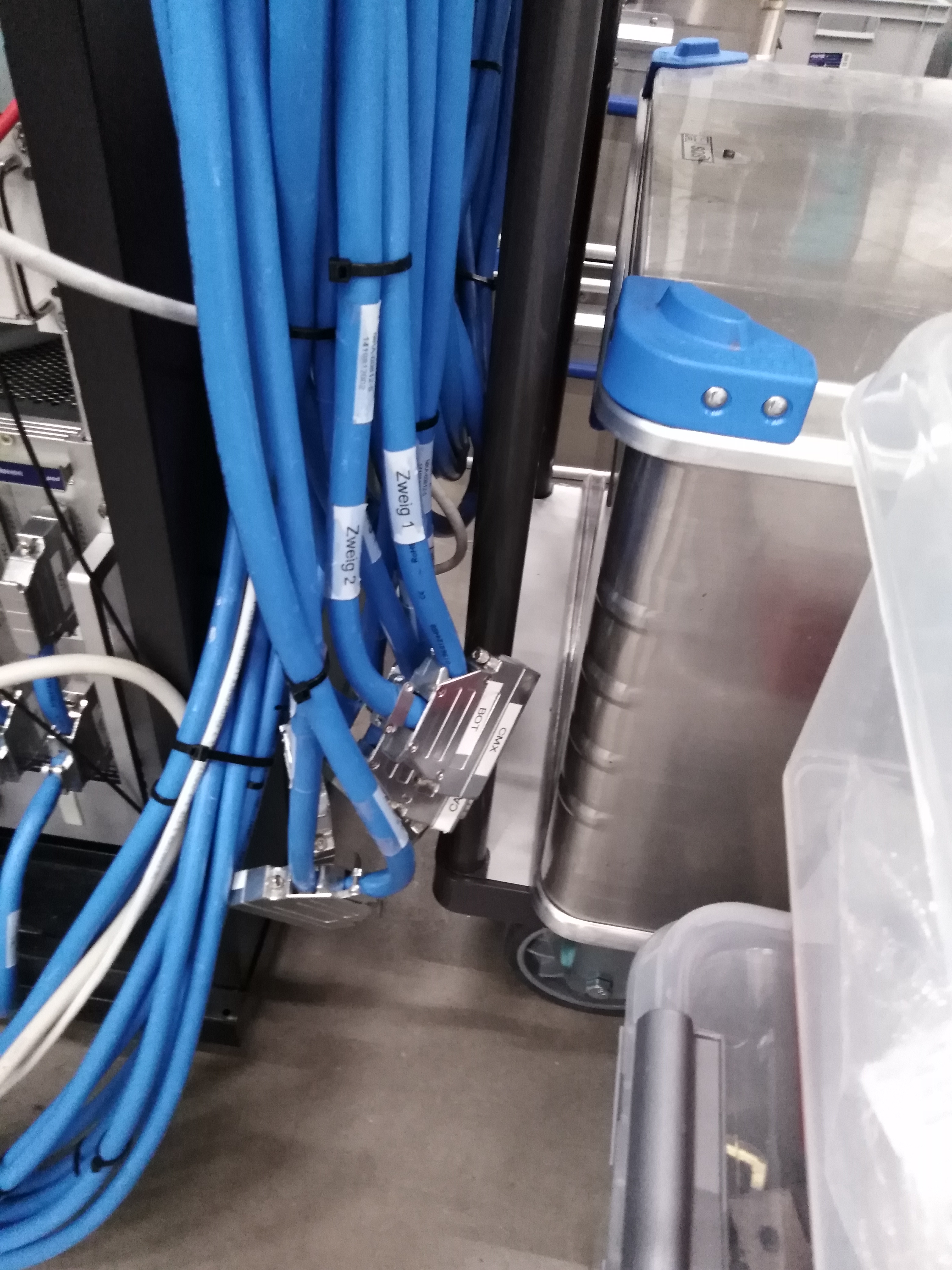
Fig. 5.16 The side of the MPOD cables that need to be plugged into the in-vacuum electronics housing of the pnCCD as discussed previously in inVacuumCableConnection.
5.4. The Vacuum System’s Hardware
There are many cables associated with the pnCCD vacuum system. They are mostly grey color. Some could be thick yellow cables with rather large circular connectors. The SQS beamline scientists should already know how to set up these cables. Make sure the cables for pumps, valves and gauges are all connected correctly. In addition, ensure the water-cooling connections (see Fig. 5.23) and the compressed air tubes (for valves) are also set up properly. Also, pay attention to the power cables for pumps and gauges, etc. Instead of explaining how to connect these cables, the pictures of some of the more important valves, gauges and pumps are shown in this section.
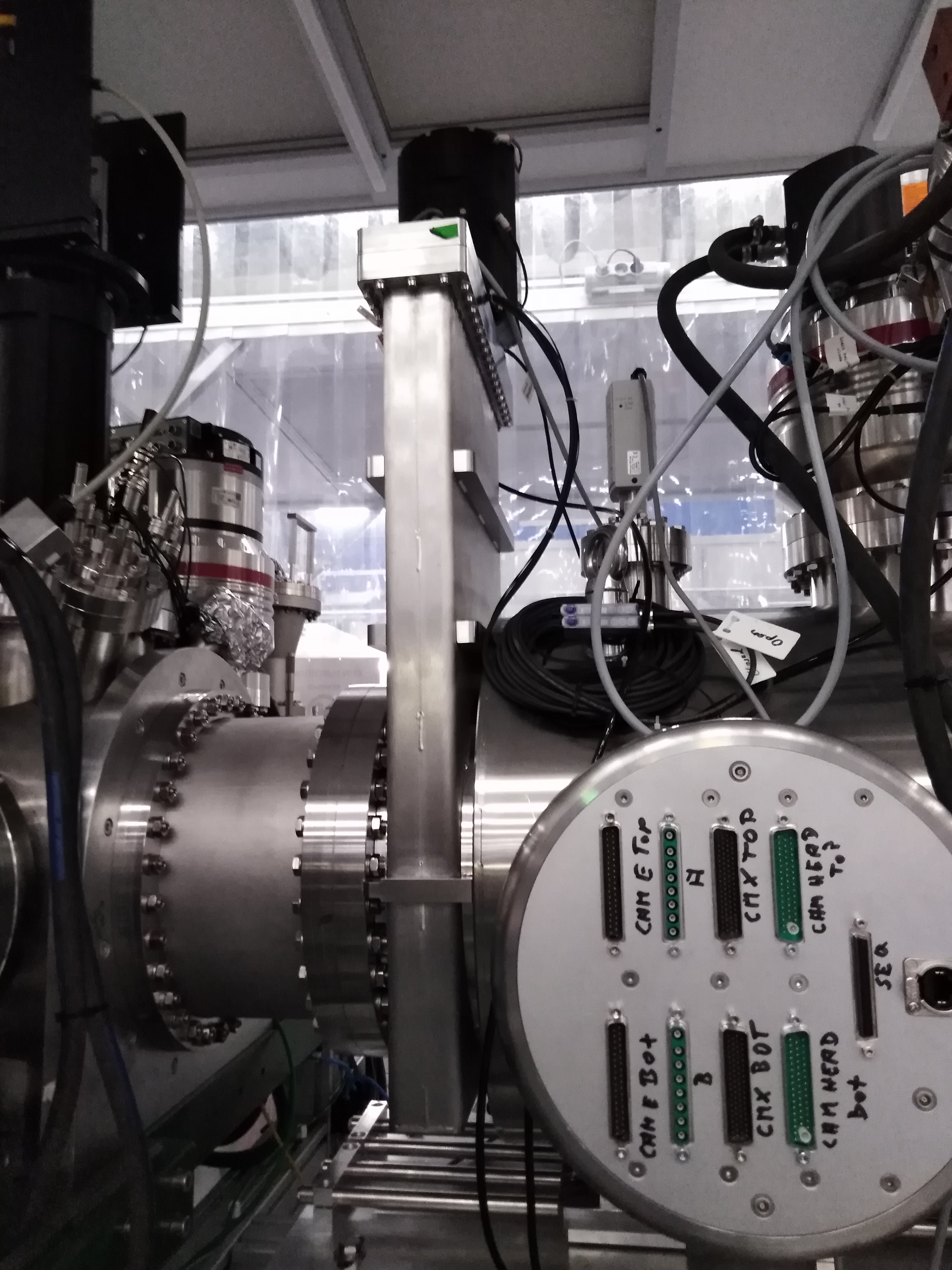
Fig. 5.17 The \(V_{2}\) valve together with the \(P_{CCD, low}\) cold cathode gauge.
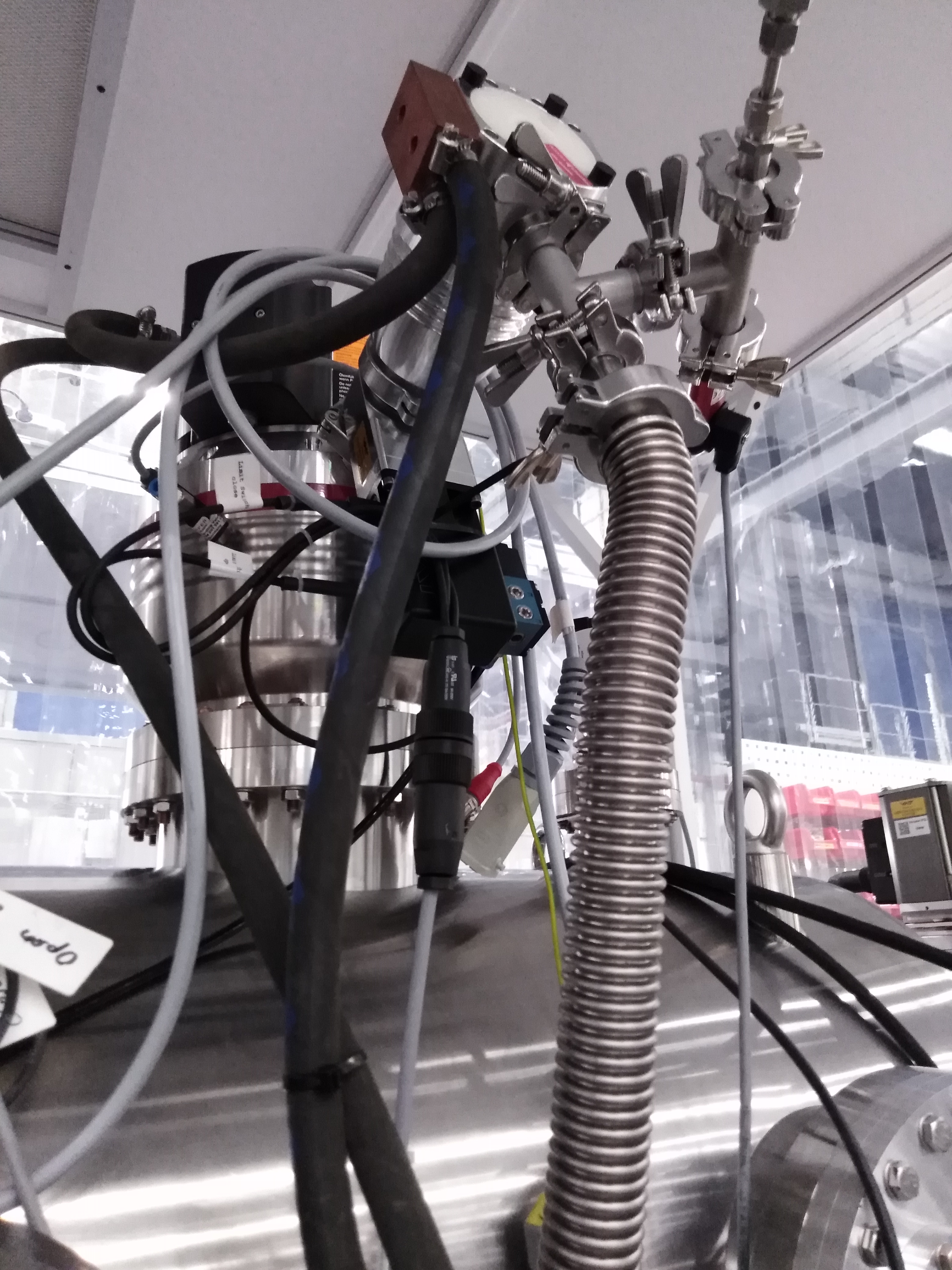
Fig. 5.18 The Pfeiffer HighPace 1200 \(TP_{1}\) and Pfeiffer HighPace 80 \(TP_{2}\) turbo pumps separated by a KF-40 \(V_{3}\) gate valve.
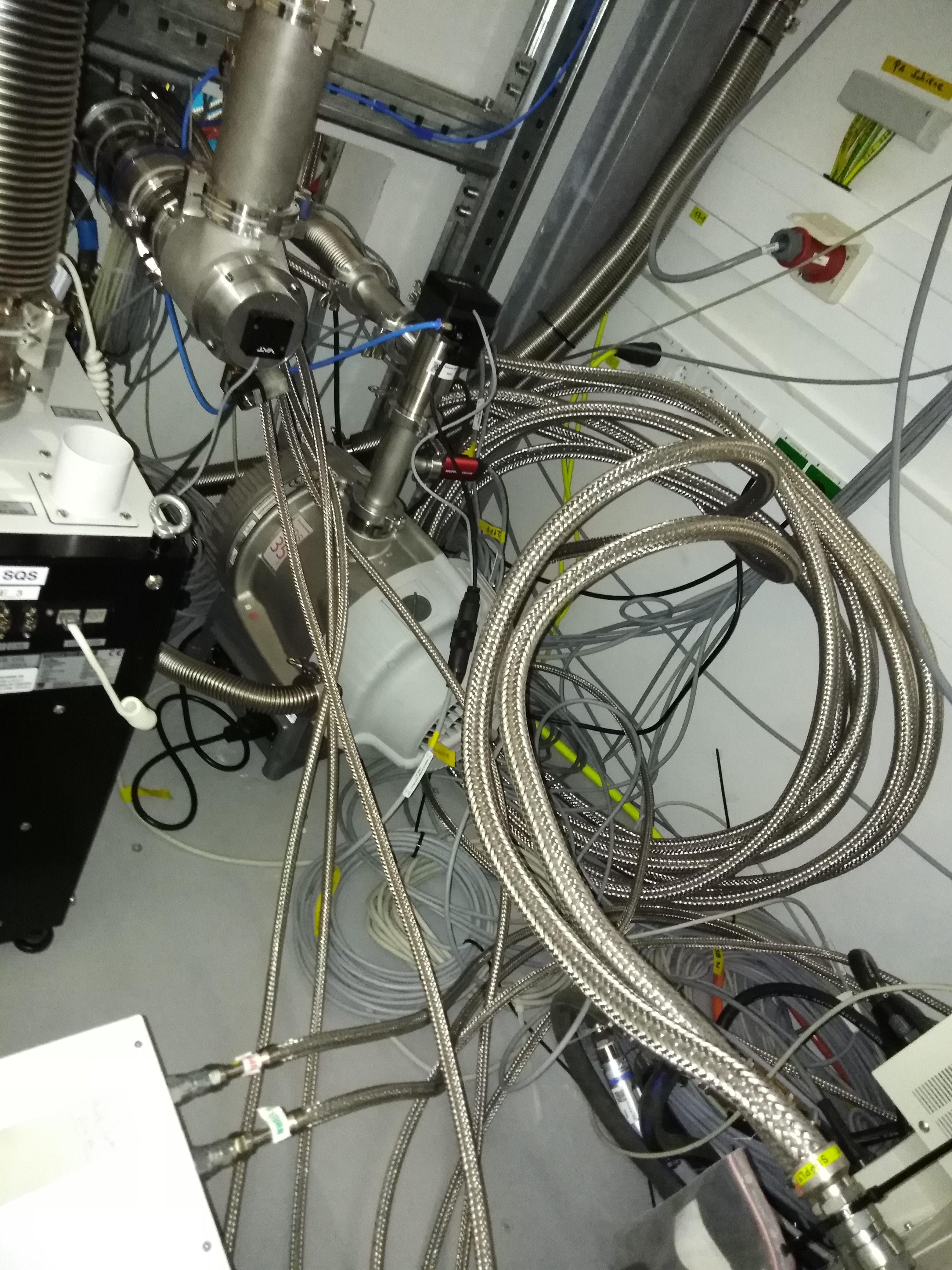
Fig. 5.19 The SQS foreline pump is buried under the long cooling lines of the pnCCD chillers. This pump is located inside the utility room in the SQS hutch.
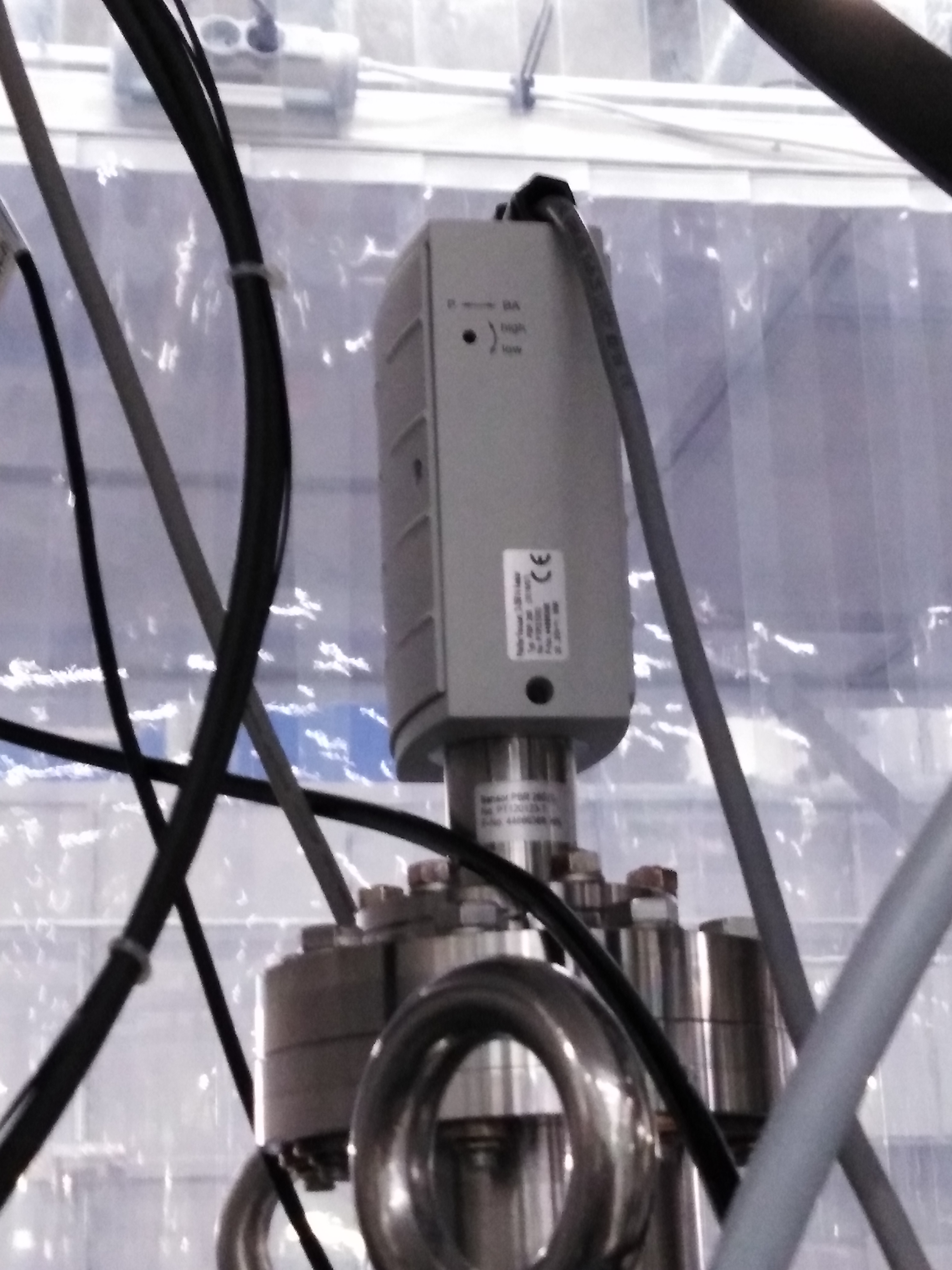
Fig. 5.20 The \(P_{CCD, low}\) cold cathode gauge.
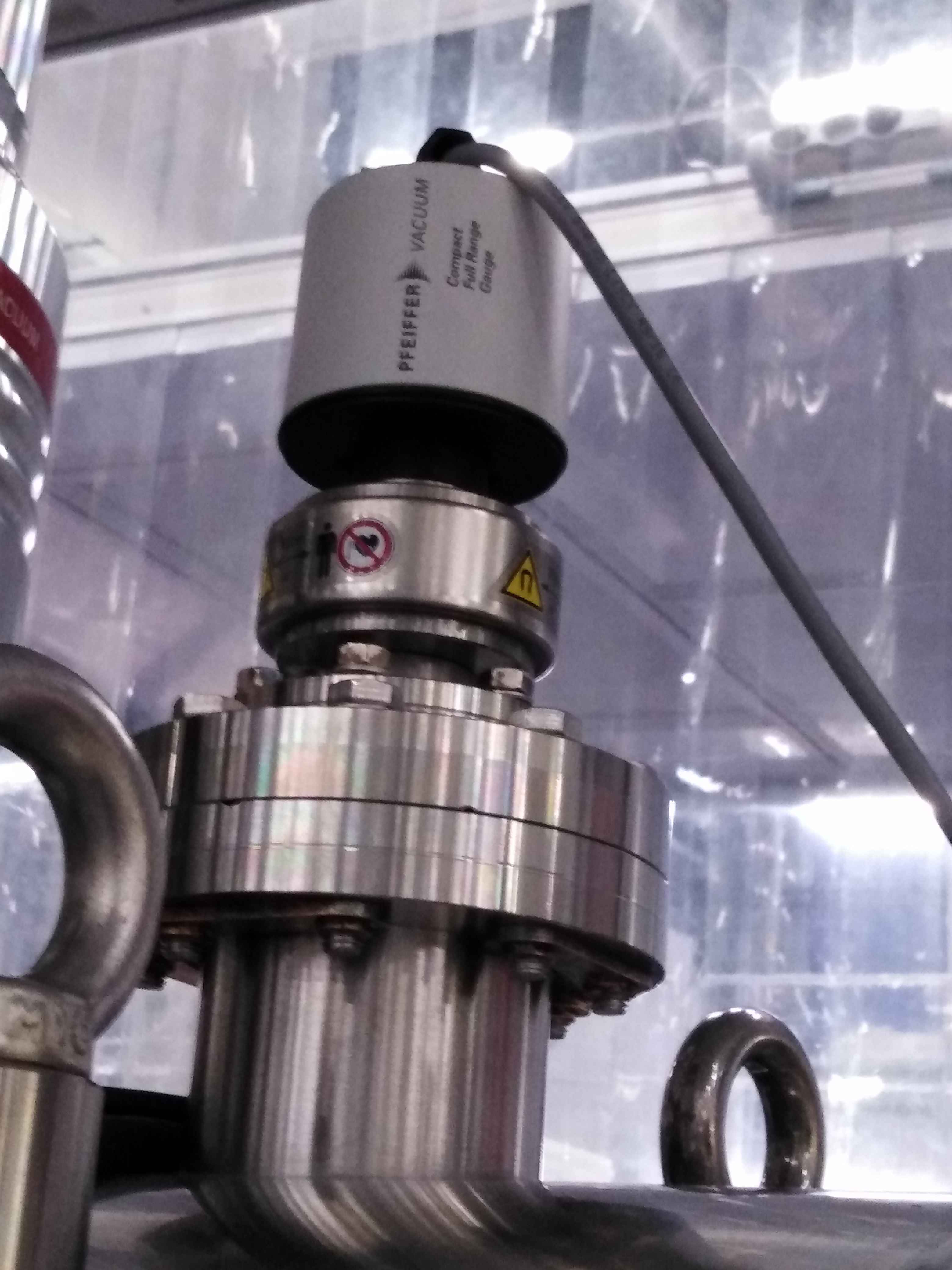
Fig. 5.21 The \(P_{CCD, high}\) full range gauge.
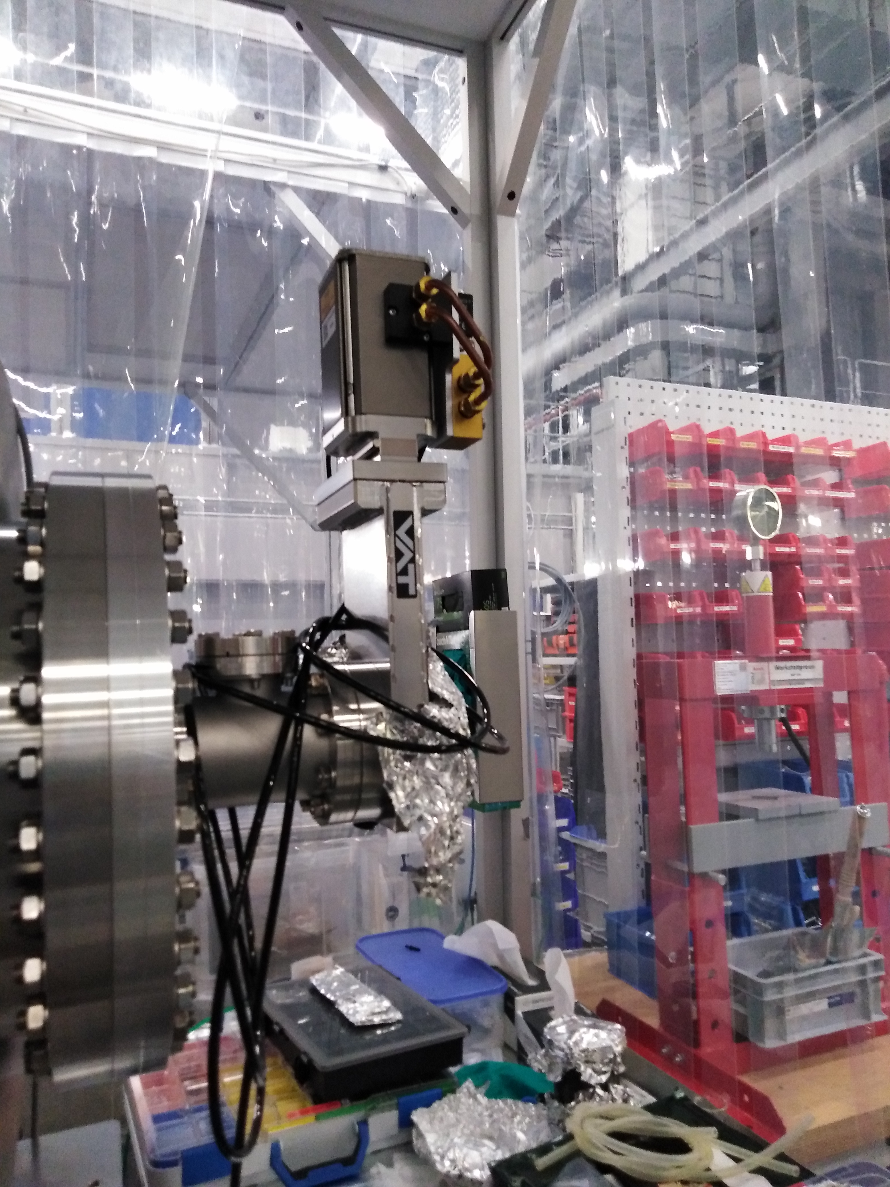
Fig. 5.22 The \(V_{1}\) valve at one end of the pnCCD chamber.
Fig. 5.23 The pnCCD water-cooling system on the side of the pnCCD chamber.
5.5. Hardware Setup for the pnCCD Cooling System
5.5.1. The pnCCD Chillers
To set up the pnCCD chillers:
- Connect the cooler control units and the PCC chiller units to their independent UPS system (see Fig. 4.11). Make sure the powers are provided and everything is grounded.
- Connect the cooler gas lines carefully and properly. First, connect the supply/return sides of the gas lines to the pnCCD chamber (see Fig. 5.24). Then connect the other side of gas lines to the chiller units (see Fig. 4.14). Make sure you track which line goes where (which supply line goes to which chiller and which return line goes to which chiller) and properly connect them, Also, first connect the return line and then the supply line per chiller. When you are connecting the supply line, act fast and avoid introducing air into the system.
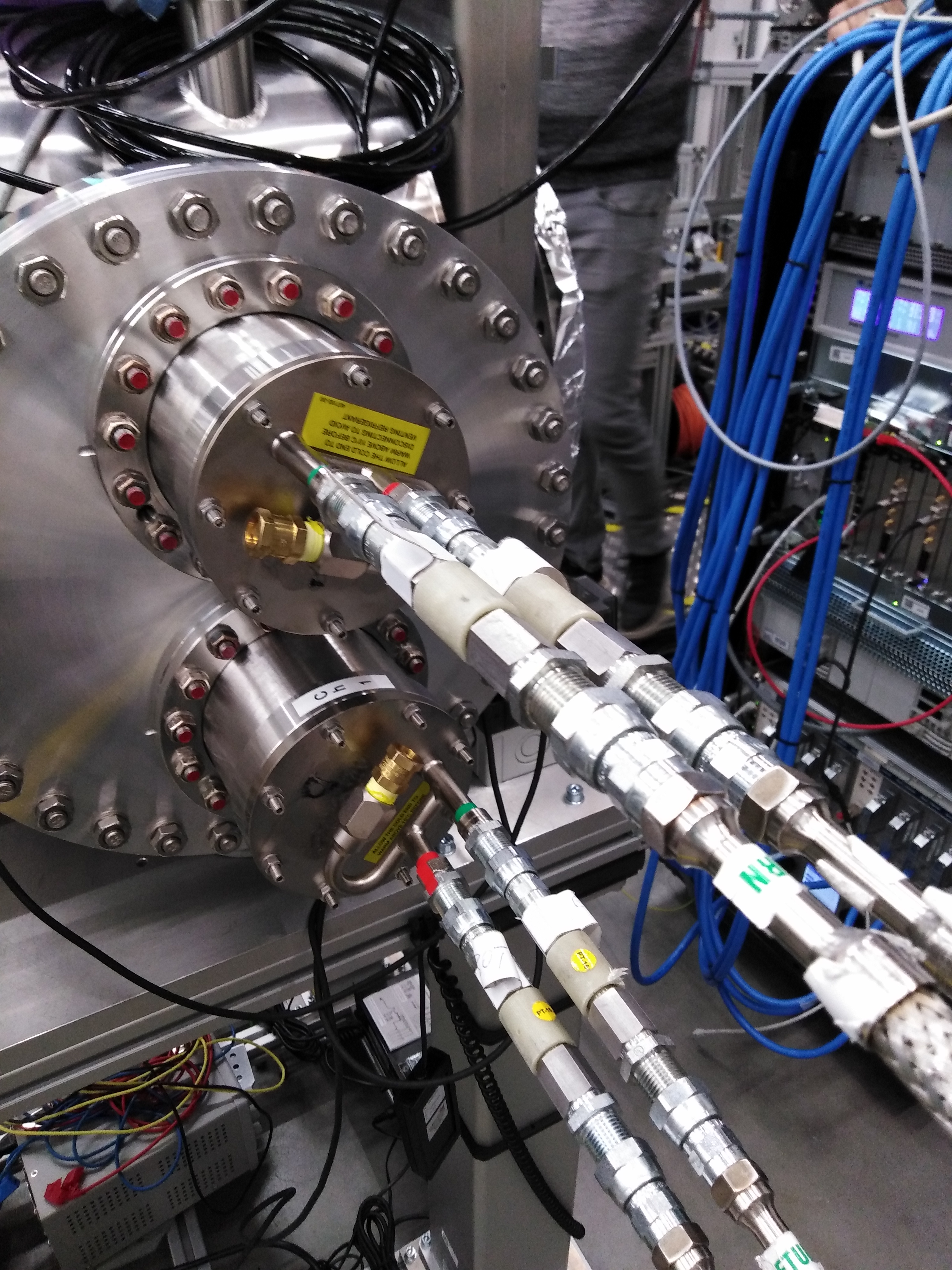
Fig. 5.24 Each pnCCD chillers have two gas lines for PT-30 supply and return (to the compressor).
5.5.2. The Lake Shore Unit
Connect the Lake Shore cables as shown in Fig. 5.25.
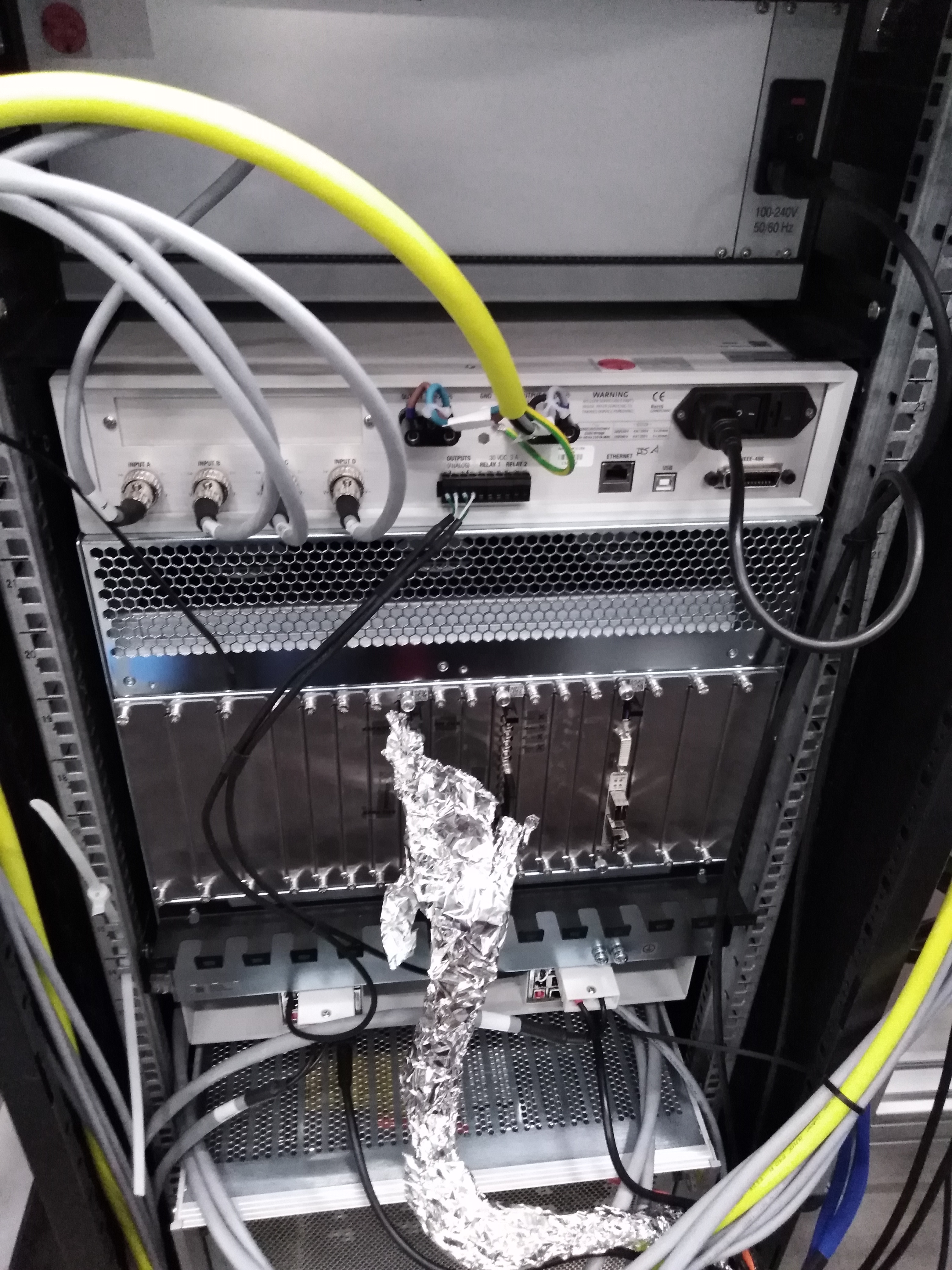
Fig. 5.25 The back of the Lake Shore temperature control unit. The 4 grey cables are connected to the the PT-100 temperature sensors measuring: i) the temperatures of the top and bottom pnCCD modules (2 temperature sensors) and ii) those of the top and bottom cold heads (another 2 temperature sensors). The power cable is the black cable shown on the right. The yellow/green striped cable is the grounding cable. The other cables near the grounding cable are associated to the 4 heaters to heat the top and bottom pnCCD sensors and the top and bottom cold heads in order to regulate the temperatures. The two heater outputs on the right are 50 W maximum (for heating pnCCD modules), while those on the left are 100 W maximum (for heating the cold heads). Finally the two cables connected to the analog inputs of the power strip are connected directly from the output terminals to the power supply programming input. With these two cables, the heaters’ percentage output can be controlled.
5.6. pnCCD Interlock System Setup
To set up the vacuum interlock:
- The \(P_{CCD, high}\) full range pressure gauge on top of the pnCCD chamber (see Fig. 5.21) should be connected into input channel 2 of the Maxigauge (see Fig. 4.18).
- The relay for sensor/channel 2 of the Maxigauge should be manually enabled.
- The, low and high pressure setpoints for channel 2 of the Maxigauge should be manually set to \(10^{-5}\) mbar and \(10^{-4}\) mbar, respectively.
To set up the MPOD interlock:
- There is a D9 connector in the cables that are connected to the interlock box (see Fig. 4.17) of the Maxigauge (see Fig. 4.18). This D9 connector should be connected into the bottom of the MPOD crate (on the front side, to the left of the Iseg HV power supply). If the Maxigauge relay for sensor/channel 2 is enabled manually, the D9 cable provides \(+5V\) signal to the MPOD crate and then the 88 voltage channels of pnCCD/CAMEX are not interlocked and one can turn CAMEX/CCD ON/OFF. Otherwise, if the relay is disabled, the D9 connector will have 0 V on its pins, and in this case the 88 voltage channels of pnCCD/CAMEX are interlocked (magenta color in Karabo, see Fig. 6.3) and one cannot turn CAMEX/CCD ON.
To be able to turn the pnCCD chillers on:
- Connect the cable labelled as
To the Chiller(the cable is connected to the interlock box of the Maxigauge).- Ensure that the interlock is set properly and is working fine.
- Ensure the gas lines are properly connected to the pnCCD chamber (see Fig. 5.24).
- Ensure the chillers’ UPS system (see Fig. 4.11) is properly set up.
- Ensure the vacuum in the pnCCD chamber is better than \(10^{-7}\) mbar.
Warning
- Note that there is a flaw with the pnCCD hardware interlock system. One cannot pump down the pnCCD chamber from atmospheric pressures with this interlock active because the pressure has to go below \(10^{-5}\) mbar for the interlock to be set. Therefore, to pump down the system from scratch, one has to remove the interlock and in order to open valve \(V_{2}\), one has to connect the \(V_{2}\) valve to the \(V_{3}\) cable.
5.7. pnCCD Motion System Setup
The motor cables are blue and the encoder cables are green (see Fig. 5.26). They should be connected to the patch pannel shown on Fig. 5.27. The black cables connected to the patch pannel should be connected to their associated input on both sides of the pnCCD chamber as shown in Fig. 5.28 and Fig. 5.29.
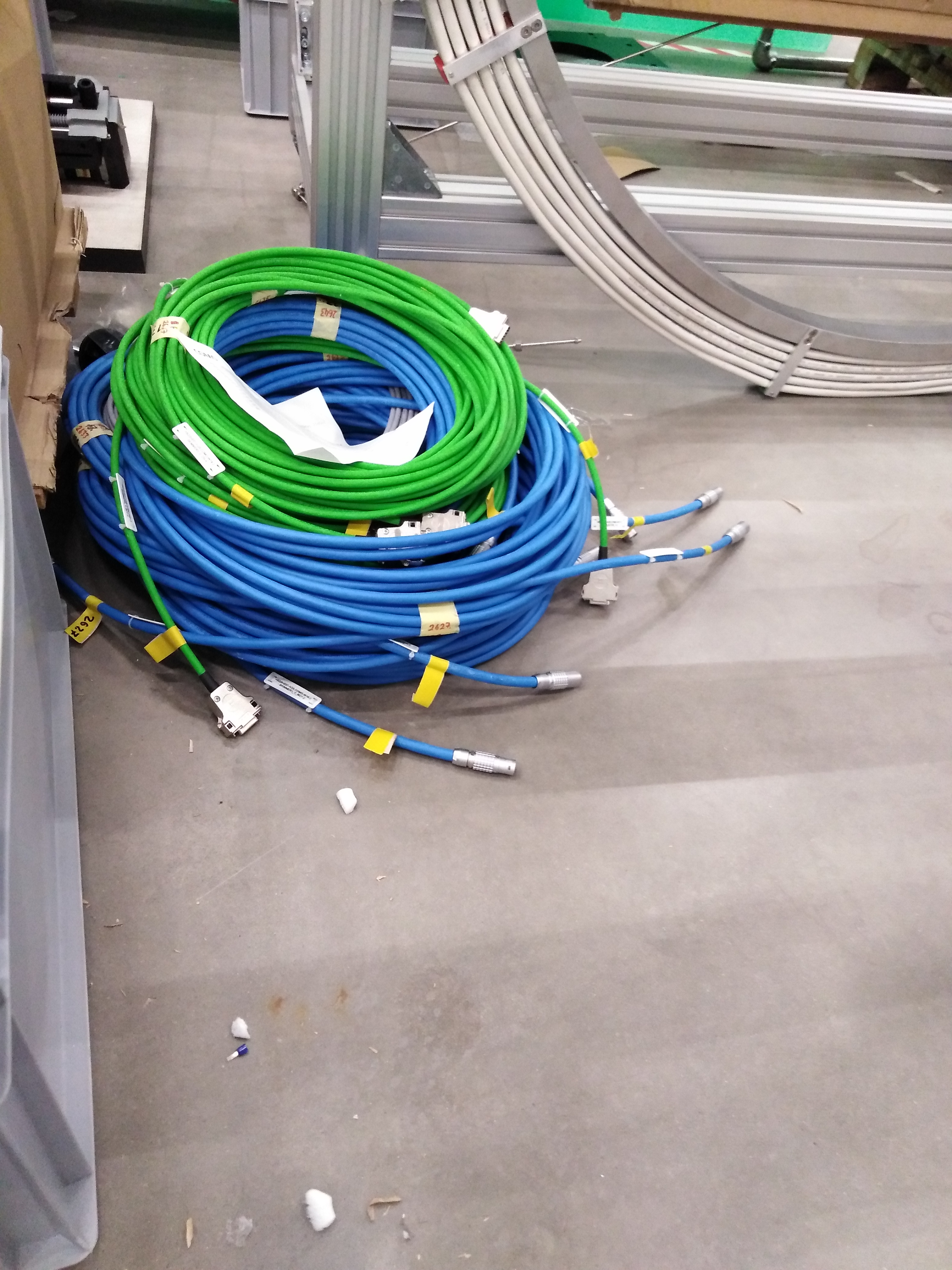
Fig. 5.26 The motor (blue) and encoder (green) cables for the pnCCD motion system.
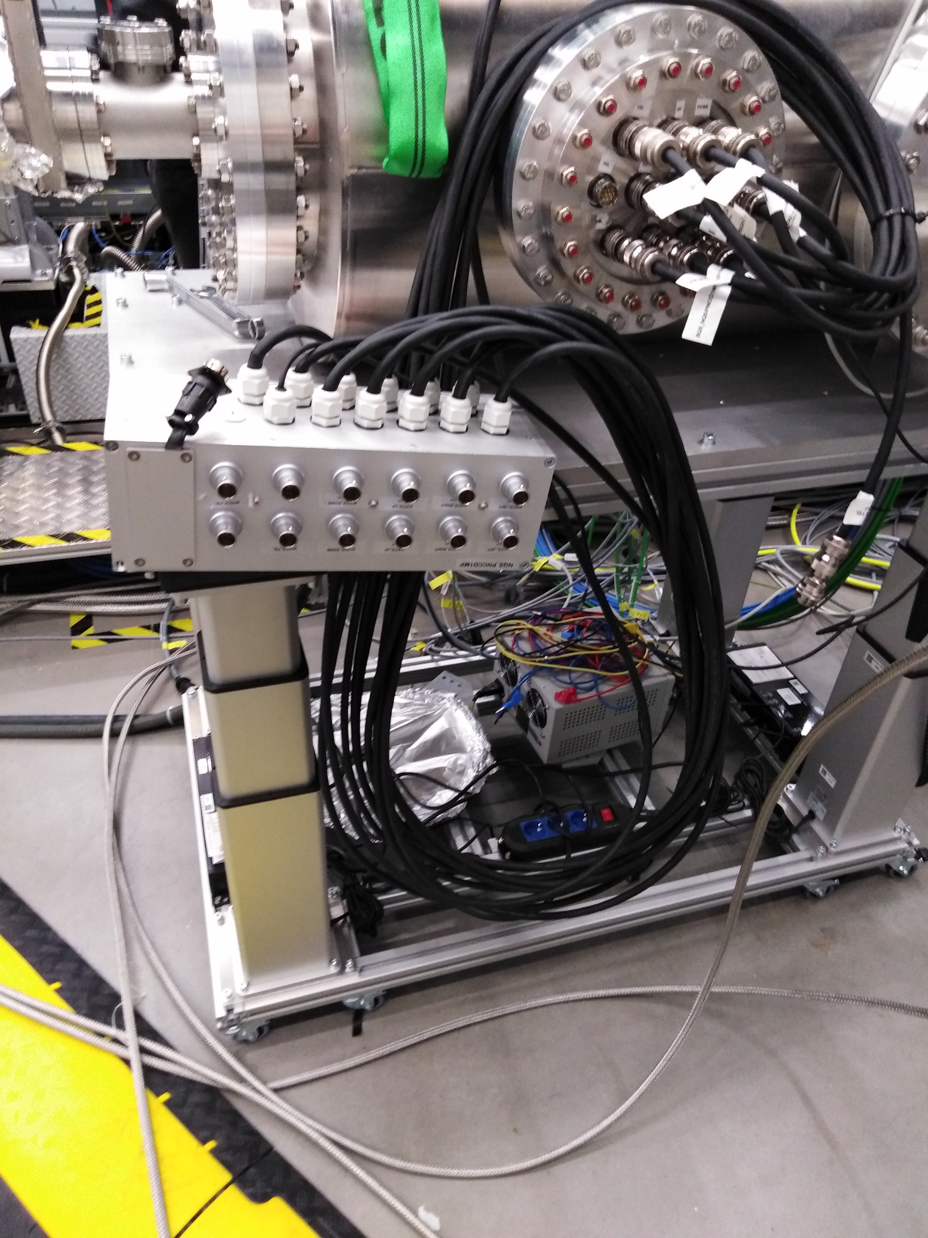
Fig. 5.27 The patch pannel for the motor and encoder cables of the pnCCD motion system. The little black cable on the left which is separated from all others is where the power cable should be connected. Do not forget to connect this cable; otherwise, no motion can be achieved.
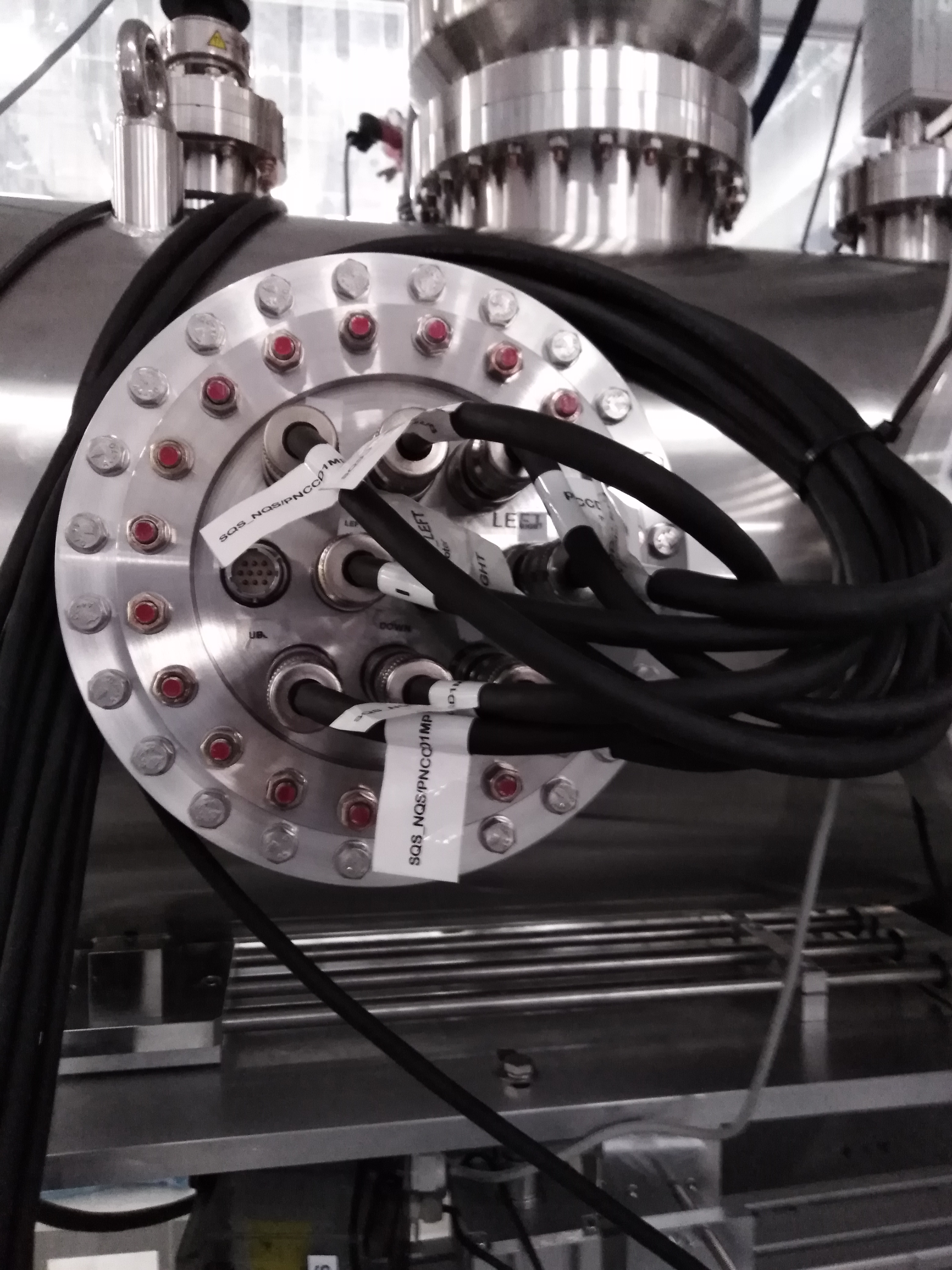
Fig. 5.28 The black cables connected to the patch pannel of the pnCCD motion system (see Fig. 5.27) need to be connected to both sides of the pnCCD chamber.
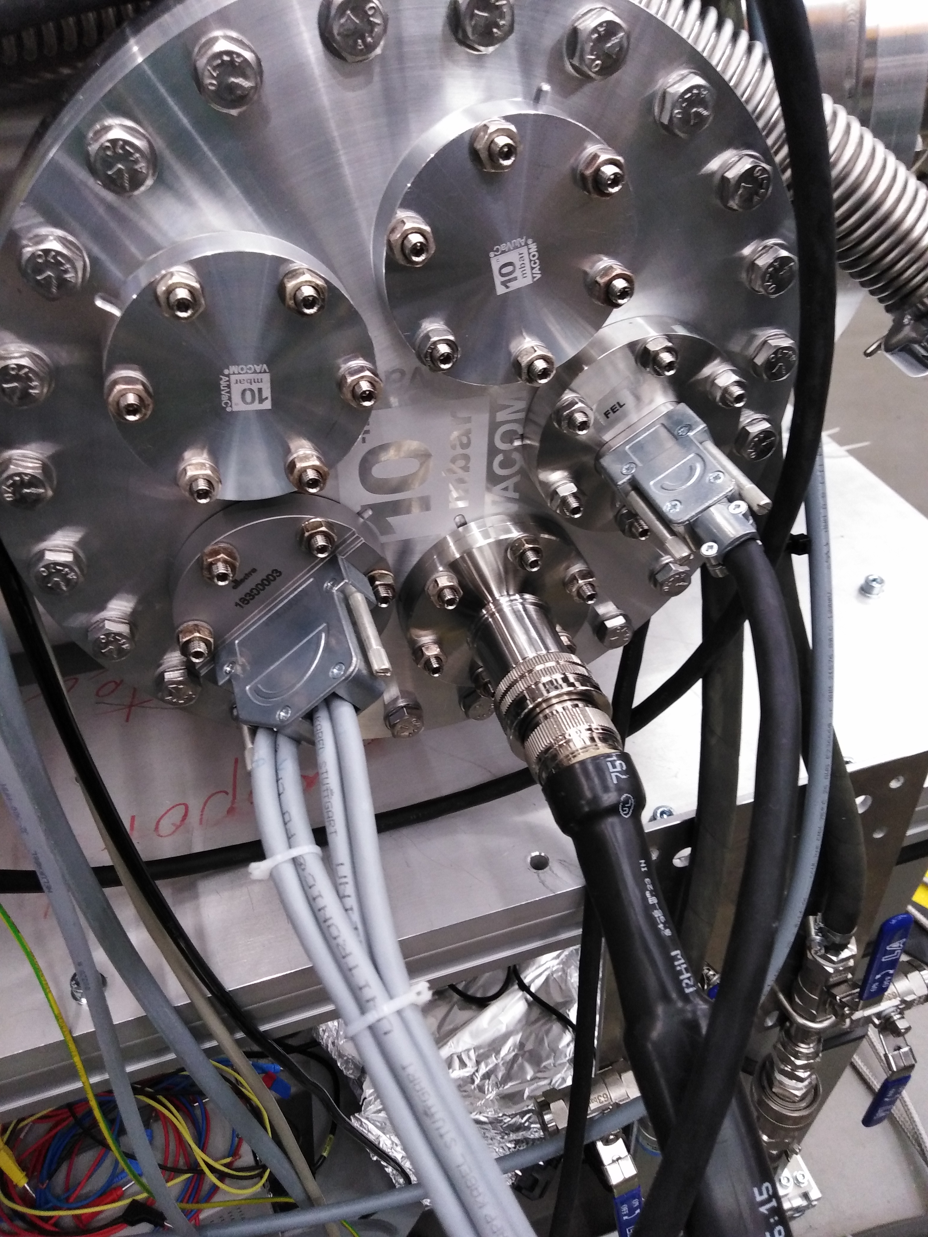
Fig. 5.29 The black cables connected to the patch pannel of the pnCCD motion system (see Fig. 5.27) need to be connected to both sides of the pnCCD chamber. The cable with signal from the FEL motion (along the beam direction) was damaged some time ago and instead, we use an in-house made D9 connector to achieve this latter motion.