6. pnCCD Control Software
6.1. Karabo
Similar to all other detectors at European XFEL, the pnCCD detector is operated via Karabo control framework (see Karabo).
The pnCCD Karabo control system monitors the pnCCD vessel and any other device connected to it (such as vacuum, temperature control, motion systems, etc.). The status information is written to files compatible with the slow control data and file format.
6.1.1. Karabo GUI
To open the Karabo software, one needs to first start Karabo services, e.g., the GUI server and the Karabo GUI.
On a control computer in the SQS hutch/control room, open a terminal and make sure the
sqsopuser is logged in. From the home directory, execute the following commands:1 2 3
source karabo/activate
karabo-start
karabo-gui &
Alternatively, you can go to the desktop on the aforementioned computer and find the
Karabo GUIfile. Double click on it and it will open Karabo version 10.2.4. Follow the next step once the window is opened.To connect to the Karabo server, click on the button with a plug icon on the upper left of the GUI. In the pop-up window, leave all the default settings alone, make sure the username is
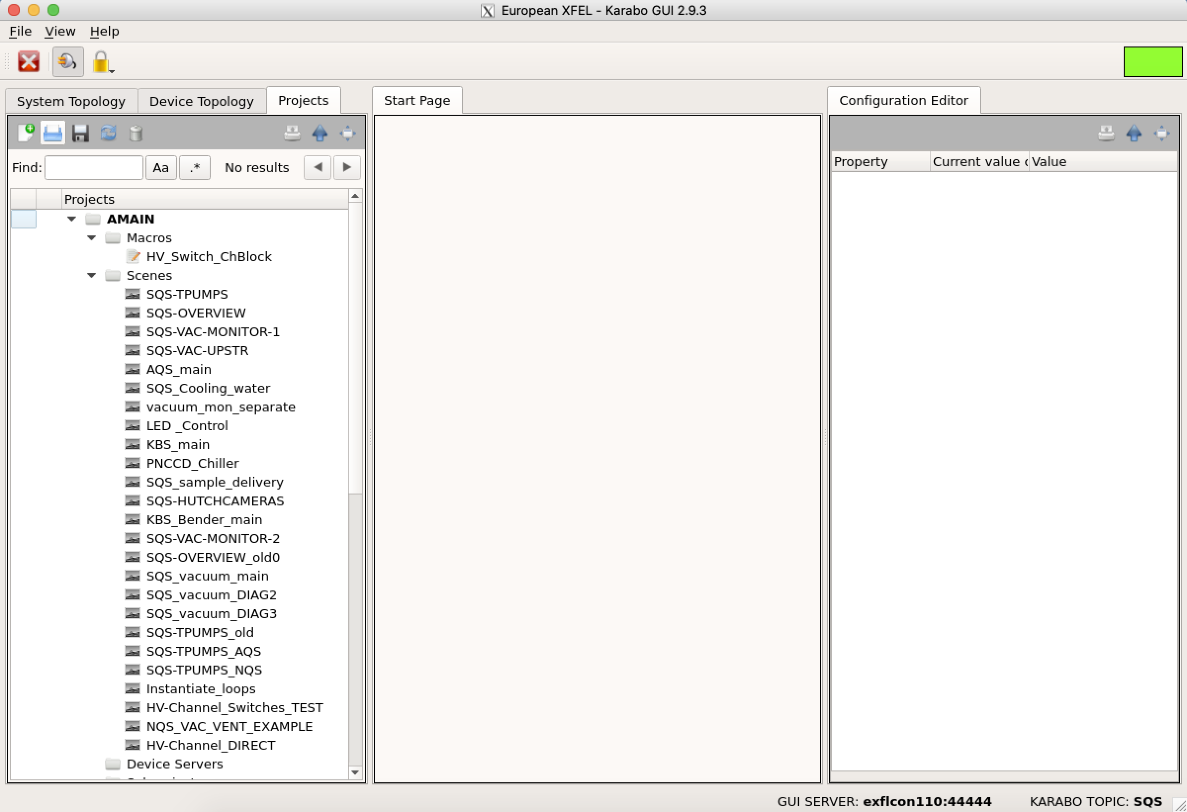
admin(if you are not employed by the European XFEL and are a user, please choose theuserusername instead. Users should NOT log into Karabo with the admin username) and click onconnect. In theProjectsmenu on the top left of the GUI, click onLoad an Existing Project, which looks like a blue folder. A window pops up called “Load Master Project”. ChooseSQSon the top drop-down menu and double click on theAMAINproject (or click onAMAINand click onLoad). Wait until the square on the top right corner of the Karabo window (see Fig. 6.1) turns green.
Karabo scenes are found under Scenes directory/menu of any Karabo project (if the project has any scenes). Double clicking on any of the available scenes will open that scene.
In general, any Karabo project has numerous servers and devices, all of which are listed under Device Servers. Each Karabo device has 6 possible states:
- UNKNOWN: in case of any timeout errors
- ERROR: in case of any other errors such as the absence of a proper connection to the device
- OFF: after initialization
- ACTIVE: after auto-start and when applying basic configurations to the device has finished
- ON: after main power is enabled and all other power sources are also on
- ACQUIRING: during data acquisition
- PASSIVE: the device is OFF (some devices have this state)
- CHANGING: some automatic check is running, do not interfere
To find a device, go to System Topology menu found on the top left corner of the Karabo window and search for the device. You can also do the search in Device Topology menu, where the devices are listed based on the subprojects.
Generally, all the SQS Karabo devices that are related to the SQS PLCs can be found by going to Karabo System Topology and searching for cppSever/sqs_loop_15.
To find a server, go to System Topology menu and click on Srevice Manager menu found on the top left corner. A window pops up, where the servers are listed. From there, a server can be stopped, started or killed. Be extra careful when stopping/killing a server. Make sure you know what you are doing. In case of problems, contact Controls OCD. From this window, you can also see the status of a server and know if it is up and running.
6.2. pnCCD Karabo Scenes
From the AMAIN project, go to Subprojects menu (found on the left hand side of the Karabo page, scroll down till you see Subprojects). Expand the menu and find SQS_PNCCD subproject. Expand the latter menu. Under Scenes, open the following Karabo scenes for the pnCCD:
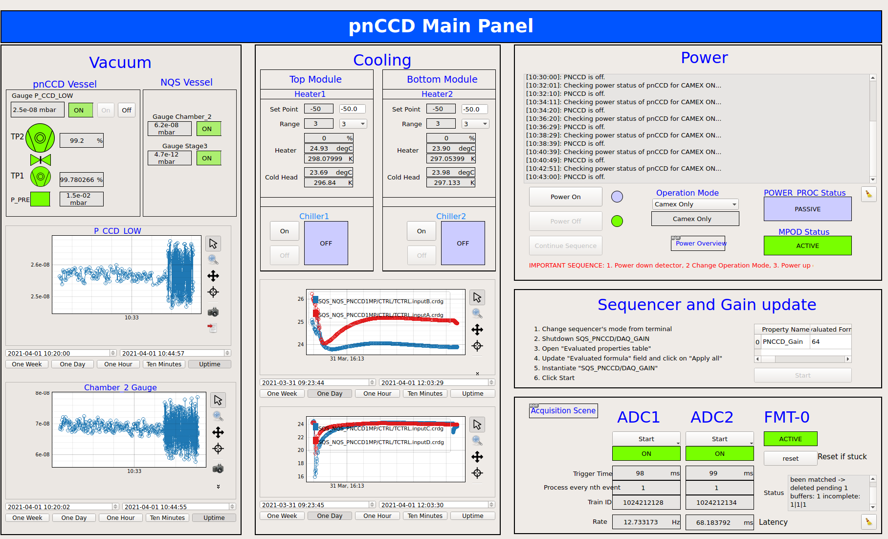
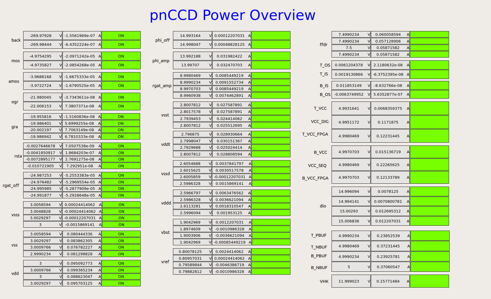
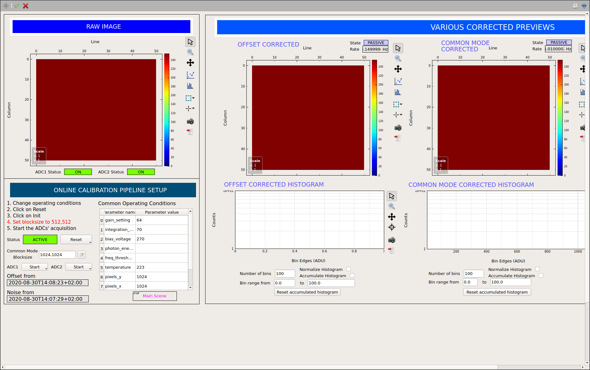
pnCCD_Main: With this scene (see Fig. 6.2), you can control some vacuum gauges; check the status of vacuum pumps, valves, gauges and chillers; control the pnCCD chillers; set the temperature setpoints and heater ranges; check the history of temperatures and vacuum pressure; set the operating mode of pnCCD; power up/down the detector; check the status of FastADCs; and start ADC acquisition.pnCCD_Acquisition: With this scene (see Fig. 6.4), you can see the raw and corrected data; upload new dark constants; and see the histograms of corrected data.pnCCDPowerOverview_New0: With this scene (see Fig. 6.3), you can check the status as well as the measured (readback) bias voltages of all 88 voltage channels of pnCCD.
These three scenes are all you need to operate the pnCCD and observe the images/histograms.
