9. Troubleshooting
This chapter guides you to troubleshoot problems that may occur during pnCCD operation. If you are in doubt or cannot fix the issue at hand, please contact DOC. The pnCCD elog also has a lot of useful details, tips, pictures and valuable and updated information regarding the hardware, operation and data analysis of pnCCD. Please consider consulting the elog together with this manual.
Tip
- To solve the problems with Karabo, you may want to call Controls OCD.
- General problems with the DAQ system can be solved by contacting ITDM OCD.
- In addition, for problems with ExtraFoam, Metro and/or Karabo bridge, contact DA OCD.
9.1. Maxwell Cluster Is Unaccessible
If the runs cannot be migrated from the Meta Data Catalog, or you are failing to tunnel to the Maxwell cluster, email ITDM support. They will contact DESY and it may take a while to fix the issue.
9.2. The pnCCD Gain Setting Is Wrong at the End of the Dark Report
If this is the case, you have forgotten to change the gain setting manually in Karabo before starting the run. Every time you need to start a run, first make sure the PNCCD_Gain value at the bottom of the Configuration Editor of the SQS_NQS_PNCCD1MP/MDL/DAQ_GAIN Karabo device is the same as the gain setting shown on the sequencer’s console (see Fig. 8.2), and that both values are the desired gain setting.
If the PNCCD_Gain value in the SQS_NQS_PNCCD1MP/MDL/DAQ_GAIN Karabo device is not what it should be, see GainSaving.
Note
- If the pnCCD gain setting is wrong on the dark report, the raw data corresponding to that dark run are also saved with the wrong gain setting. Therefore, depending on which gain setting is selected in the
SQS_NQS_PNCCD1MP/CAL/MANAGERKarabo device (seeCalibratedPreview), if you are trying to retrieve new dark constants from the online calibration pipeline, the offset and common mode corrected images could be wrong because they will be for a wrong gain setting. So, you need to scrap this dark run. Save the right gain setting in Karabo. Take a new dark run and process it. Make sure the correct gain is set in theSQS_NQS_PNCCD1MP/CAL/MANAGERKarabo device (seeCalibratedPreview). Retrieve the new offset map from the online calibration pipeline. Now, the corrected images are proper.
9.3. Problems with the Calibration Webservice
Call ITDM for problems with Meta Data Catalog.
9.3.1. Runs are Stuck
If the run is pending on the Status section of the Meta Data Catalog calibration service, ensure the run is migrated to Maxwell. If not, migrate the data and wait for a few seconds and check back the calibration webservice on Meta Data Catalog. Your run should appear blue with label In Progress (running) shortly after you migrate the data and refresh the calibration service on Meta Data Catalog.
It takes about 4 to 5 minutes for the dark runs to process and at least 20 to 30 minutes for the calibration runs (instantiated from the Meta Data Catalog) to be processed. Please be patient. Also do not forget to reload the webpage frequently.
If the status of your run is In Progress but it is taking much longer than anticipated, call DOC and ask them to notify the calibration team.
9.3.2. The pdf Output of the Processed Dark Run is Unaccessible
This file cannot be accessed from the SQS control PC or if you are on a network other than DESY/XFEL. If you are on these latter networks and are logged into a computer other than the SQS control PC and the problem still exists, call DET OCD and ask them to notify the calibration team.
9.3.3. Runs Are Not Appearing on the Calibration Webservice
Ensure the data are migrated to Maxwell cluster.
9.3.4. I Get an Error After Requesting Dark
Call DOC.
9.3.5. Dark Reports Do Not Appear
This is a known issue, which happens from time to time. If this is occuring, call DOC and tell them to notify the calibration team. Most of the times, the dark constants are already injected to the database, and you can retrieve them from the calibration pipeline (see CalibratedPreview). If you do the latter, make sure Offset from and Noise from fields have time stamps that are expected. If this is not true, see timeStamp.
9.3.6. Erros in the Dark Report
Depending on the type of the error:
- Sometimes, the calibration webservice encounters strange problems and the dark runs are processed properly; however, the report shows errors. To ensure this is not the case, try to retrieve the dark constants using the online preview (see
CalibratedPreview). If the offset and noise time stamps are what you expect them to be (they correspond to the date and time of your desired dark run), then you are all set. Just ignore the errors in the dark reports.- You may only need to reprocess the same run (see
DarkRuns) to solve the issue.- If the error indicates that the dark constants already exist in the database, you have processed the same dark run twice and these constants are already injected to the database on the first trial.
- If the error is something else other than those mentioned here, contact DOC.
9.4. Problems with Calibrating/Recalibrating Runs via Meta Data Catalog
9.4.1. No Calibrate/Recalibrate Button
On the Runs page of the Metadata Catalog, do NOT click on the blue button with Runs in the middle of the button and some horizontal lines on its left side. Instead, click on Runs menu to the left of Team menu (see Fig. 9.1). There you should see the run numbers corresponding to the runs you want to calibrate. It might take a few minutes for the runs to appear on the list (you will also need to reload the page manually to see the new runs).
If the problem still exists, it may be because you do not have the required permissions, in which case, ask the SQS members to give you the required permission. If you have the necessary permissions but the button is still not observed, contact DOC/ITDM.
9.4.2. Inactive Calibrate/Recalibrate Button
In this case, you do not have the required permissions. Ask the SQS members to give you the required permission. If you have the necessary permissions, and the button is still inactive, contact DOC/ITDM.
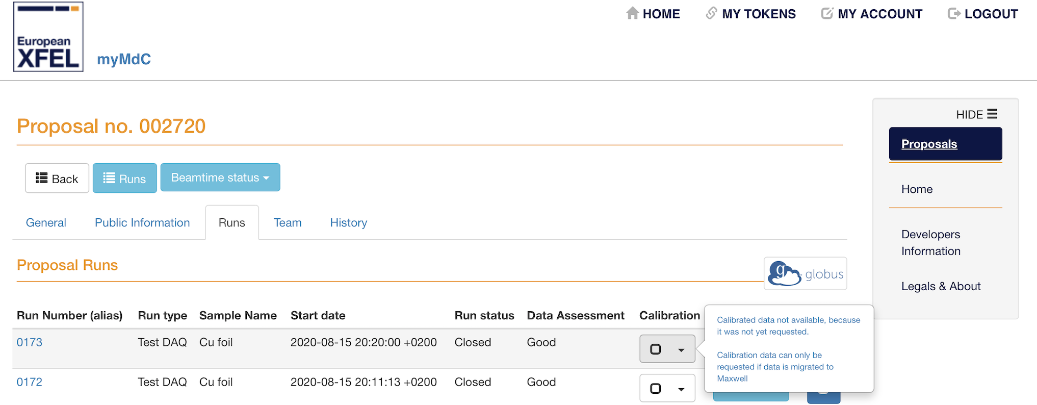
Fig. 9.1 The (Re)calibrate button is inactive if you do not have the necessary permissions for a particular proposal.
9.4.3. Other Problems
Notify the SQS members and contact DOC/ITDM if necessary.
9.5. Problems with the Online Preview
9.5.1. The Offset Time Stamp Is Not What It Should Be
Check the Common operating conditions properties on the pnCCD_Acquisition scene, which are set by the SQS_NQS_PNCCD1MP/CAL/MANAGER Karabo device (see CalibratedPreview) and make sure they are the same as those of the dark run of interest. If not, carefully follow CalibratedPreview.
If the abovementioned properties are correct and yet the timestamp is not what you expect, this is because:
- The dark run of interest was not processed properly. See
badDarks.- If the above is not the case, most likely the dark run of interest has a wrong gain setting. See
gain.
9.5.2. The Offset from and Noise from Fields on the pnCCD_Acquisition Scene are Empty
In this case, no dark constants (offset, noise and bad pixels maps) are found with the parameters/conditions identical to those of the desired dark run. The calibration database will look for the most recent dark constants with the same gain, bias voltage (to \(\pm 5\) V) and temperature (to \(\pm 5\) degK) settings as those of the dark run of interest. If no dark constants are found:
- either the dark run was not processed properly, in which case, check the dark report (see
DarkRuns) and make sure it is error free. If at the end of the report, it is mentioned that the constants are not injected to the database, seebadDarks.- or the
Common operating conditionsproperties set by theSQS_NQS_PNCCD1MP/CAL/MANAGERKarabo device (seeCalibratedPreview) are not the same as those of the dark run of interest. In this case, carefully followCalibratedPreview. Also make sure what you have done for taking the dark run of interest is what is explained inDarkRuns. If not, you may need to take a new dark run correctly.- If the problem does not go away after trying the above, cal DOC and ask them to notify the calibration team.
9.5.3. The Common Mode Corrected Image Is Stuck
Check the SQS_NQS_PNCCD1MP/CAL/CORR_CM Karabo device (see OnlinePreviewDevices). Make sure it is instantiated and is in ACTIVE state. If the device seems to be OK and the problem still persists, it is because:
- Sometimes, the
SQS_NQS_PNCCD1MP/CAL/CORR_CMKarabo device causes a massive memory leak. The cause is unknown and still under investigation. If this issue is taking place, you would observe that the common mode corrected image gets stuck and the correspondingRatefield (on thepnCCD_Acquisitionscene) shows values far less than 10 Hz or unusually large values. In this case, call DOC and shut down theSQS_NQS_PNCCD1MP/CAL/CORR_CMKarabo device. You will not be able to use the common mode corrected preview until this issue is resolved by the Controls group.
9.5.4. The Offset Correction Karabo Device Is in Unknown State
This UNKNOWN status happens usually for the first device in the calibration pipeline per detector. This means that the state of the SQS_NQS_PNCCD1MP/CAL/CORR_OFFSET Karabo device will always be UNKNOWN for the pnCCD offset correction Karabo device. Therefore, this is OK. Just ignore it and make sure the SQS_NQS_PNCCD1MP/CAL/CORR_CM device is in ACTIVE state. If not, contact DOC.
9.5.5. Raw Image Is Stuck
- Make sure the sequencer is running (see
SequencerCTRL).- Go to the
pnCCD_Mainscene and make sure both ADCs are inAcquiringstate. If they are inONstate, click onStartbutton for both ADCs.
9.5.6. Corrected Images are Stuck
- Make sure the sequencer is running (see
SequencerCTRL).- Go to the
pnCCD_Mainscene and make sure both ADCs are inAcquiringstate. If they are inONstate, click onStartbutton for both ADCs.- Check the
SQS_NQS_PNCCD1MP/CAL/CORR_OFFSETandSQS_NQS_PNCCD1MP/CAL/CORR_CMKarabo devices (seeOnlinePreviewDevices) and ensure they are both instantiated. TheSQS_NQS_PNCCD1MP/CAL/CORR_OFFSETKarabo device will be inUNKNOWNstate and that is normal (seeOffsetUnknown). The common mode correction device should be in anACTIVEstate.- Check the state indicators above the offset and common mode corrected images on the
pnCCD_Acquisitionscene and make sure they are bothACTIVE.- If everything looks normal and the images are still stuck, call DOC.
9.6. Problems with the FastADCs
9.6.1. The FastADCs Seem to be Stuck
If the FastADCs hang and seem to be stuck (ADCs are stuck on Acquiring state but are not triggering), check the Trigger Time corresponding to both FastADCs on the pnCCD_Main scene. If the numbers are not changing:
- Check the sequencer. Make sure it is not stopped. If it is, start it (see
SequencerCTRL) using the desired pnCCD gain setting.- If the sequencer is running fine but the
Trigger Timesare stuck and theLatencyis around 60 ms and/or theRatejumps around 4-28 Hz instead of 10 Hz, there is a chance that the formatter device [1] has crashed. SeeFormatterto solve the issue.
9.6.2. The Formatter Karabo Devices Crash
If one or both of the following devices (see electronicsKaraboDevices) are suddenly shut down:
SQS_NQS_PNCCD1MP/CAL/PNCCD_FMT-0SQS_NQS_PNCCD1MP/CAL/PNCCD_FMT-1
the formatter has crashed. To fix this issue, do the following sequence:
- Stop the acquisition of FastADCs by clicking on the
Stopbuttons corresponding to both ADCs on thepnCCD_Mainscene. At this point, their state should turn toON(green).- Reinstantiate
SQS_NQS_PNCCD1MP/CAL/PNCCD_FMT-0andSQS_NQS_PNCCD1MP/CAL/PNCCD_FMT-1Karabo devices. If only one of them was shutdown, shutdown the other one as well and then reinstantiate both.- Go to the
SQS_PNCCDsubproject under SQS KaraboAMAINproject and findMacrosmenu. Expand this menu and right click onpnCCD_KeepAlivemacro and then click onshutdown. Then, right click again and click oninstantiate.- Right click on the macro once more and click on
Run.- Open
KeepAlive_Formatterscene underScenesmenu in theSQS_PNCCDsubproject.- Click on
Startbutton.- Now you should see some messages on the status message window on the
KeepAlive_Formatterscene (see Fig. 9.2) and the formatter device should be back up again.
- If after clicking on the
Startbutton it seems to be non responsive, you may either need to:
- Shutdown the macro, instantiate it, run it, and then press on the
Startbutton on theKeepAlive_Formatterscene several times.- Shutdown and reinstantiate the
cppDET/detlab_fmtserver (located in theSQS_PNCCD_ADCsubproject underSQS_PNCCDsubproject), then reinstantiate theSQS_NQS_PNCCD1MP/CAL/PNCCD_FMT-0andSQS_NQS_PNCCD1MP/CAL/PNCCD_FMT-1Karabo devices, and follow the above steps from step 3 onward. If after shutting down thecppDET/detlab_fmtserver, it did not come back online, call Controls OCD.
Note
- You should try to avoid using the
pnCCD_KeepAlivemacro. If you feel like you need to use this macro to make the formatter alive and functioning, one of the ADCs may have an issue and may need to be replaced (seebadADCS). Otherwise, you SHOULD shutdown this macro so that it is not used at all.
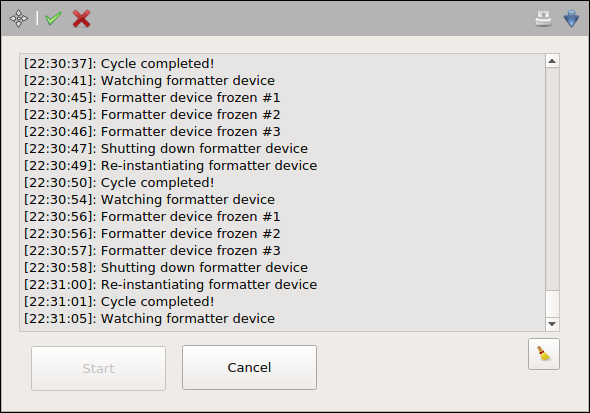
Fig. 9.2 The KeepAlive_Formatter scene while it is running (this is why the Start button is inactive here).
9.6.3. The Train IDs Are 0
If the Train ID for one or both of the ADCs (observed on the pnCCD_Main scene) is/are persistently zero and the FEL beam has no issue, contact Bruno Fernandes and Steffen Hauf (both are European XFEL employees).
9.6.4. The Trigger Does Not Make Sense
If the Trigger Time observed on the pnCCD_Main scene does not make sense (it should be something near 90 to 100 ms), contact DOC and Bruno Fernandes (European XFEL employee).
9.6.5. The ADCs Are Noisy
If one of the ADCs is problematic, you may observe an inhomogeneous noisemap (see Fig. 9.3). You will only observe this if the mode of operation is chosen to be CAMEX Only so that the CCDs are OFF and the ADCs are only triggering on the electronics noise. Also, choose a low gain setting on the sequencer so that the noise of the electronics is more dominant. In the case of a noisy ADC (more details on this issue can be found in the pnCCD elog), contact Bruno Fernandes (European XFEL employee) and ask him to replace the noisy digitizer.
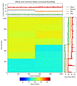
Fig. 9.3 Here, ADC2 is noisier than ADC1. The former has 10 LEMO cables while the latter has 6 LEMO cables connected to it (each cable carries the signal from one CAMEX, which, in turn, correspond to the 128 readout columns). ADC2 and ADC1 correspond to the bottom and top pnCCD sensors, respectively. However, this image is inverted because the origin (the (0, 0) location on the image) is on the bottom left corner, whereas the origin on the raw image is locate on the top left corner. Note that because ADC2 was noisy, we have already replaced the bad digitizer and this issue has been resolved.
9.6.6. Some Channels of the FastADCs Do Not Receive Any Raw Data
During the commissioning beamtime with pnCCD, or when the operation mode is chosen to be CAMEX Only, you may observe that one or more channels of the FastADCs do not receive any raw data. In this case, the ADU level (color axis) of the raw image on the pnCCD_Acquisition scene is dark blue corresponding to zero ADU. If this is the case, follow the procedure below:
- Stop ADCs acquisition (click on the
Stopbuttons corresponding to both ADCs on thepnCCD_Mainscene).- Stop the sequencer.
- Shutdown and then reinstantiate the
SQS_NQS_PNCCD1MP/ADC/PNCCD-1andSQS_NQS_PNCCD1MP/ADC/PNCCD-2Karabo devices.- Go to the
Configuration Editorwindow of both ADCs (one at the time) and click on theReset ADCbutton on eachConfiguration Editorwindow.- After resetting both ADCs, wait 5 seconds, and then click on the
Reset DDR2button on eachConfiguration Editorwindow corresponding to the ADCs. Wait 5 seconds after this step is done.- Start the sequencer.
- Start the ADC acquisition by clicking on the
Startbuttons corresponding to both ADCs on thepnCCD_Mainscene.
Note
- The behaviour of ADCs after resetting them is unpredictable. We currently do not have a systematic procedure to follow to get a nice homogeneous noisemap or to get the same raw image. Anytime the ADCs are reset, the noisemap and the raw image may look different even though the only thing that is done is resetting the ADCs.
9.6.7. There Is a Blue Light Lit on the FastADCs
The blue light is most likely due to the digitizer board using an old version of the MMC firmware. This does not influence the operation of the digitizer and the light can be ignored.
9.7. Errors While Powering Up/Down the pnCCD
You should not encounter any error while powering up the pnCCD. In the rare occasion of getting an error during this process, click on Continue Sequence button found in the Power section of the pnCCD_Main scene. This will resolve the issue. Call DOC and ask them to notify DET OCD that this has happened.
During powering down procedure, you may encounter an error complaining one of the issues mentioned below. In any case, click on Continue Sequence button found in the Power section of the pnCCD_Main scene. This will solve the issue. Call DET OCD and notify them that this happened.
- “88 channels with tag all did not finish ramping”. This error most likely occurs at the very end of the power down procedure after all voltages go down to zero. It looks like the procedure fails to turn the MPOD channels OFF.
- “POWER_U0 did not reach voltage set.”
- “Channel POWER_U9 did not reach voltage set: diff \(= -1.715 > 1.5\)“
- You may encounter some other error. In this case, take a screen capture and post it in the pnCCD elog.
If you keep getting errors during the power up/down procedure consistently, i.e., more than once, or if clicking on the Continue Sequence button did not solve the issue CALL DOC/DET OCD IMMEDIATELY.
9.8. Problems with the pnCCD Interlock System
9.8.1. pnCCD Chamber cannot be Vented
There is a flaw with the pnCCD hardware interlock system. One cannot pump down the pnCCD chamber from atmospheric pressures with this interlock active because the pressure has to go below \(10^{-5}\) mbar for the interlock to be set. Therefore, to pump down the system from scratch, one has to remove the interlock and in order to open valve \(V_{2}\), one has to connect \(V_{2}\) to \(V_{3}\) cable.
Warning
- Never vent the pnCCD chamber with the detector biased and/or cooled.
9.8.2. The pnCCD Chillers Cannot Be Turned ON
Make sure the pnCCD local interlock is set properly (see Interlock and interlockSetup). The chillers may be interlocked, in which case their status indicators on the pnCCD_Main scene are magenta color and one cannot turn them ON. Also, make sure the vacuum in the pnCCD is better than \(10^{-7}\) mbar (see vacuumHardware and OperationChapter). If the interlock is set properly and the vacuum is alright and yet you cannot turn the chillers ON, notify the SQS members.
9.8.3. MPOD Power Supply Cannot Be Turned ON
Make sure the pnCCD local interlock is set properly (see Interlock and interlockSetup). The MPOD crate may be interlocked, in which case it cannot be turned ON and the POWER PROC Status on the pnCCD_Main scene is magenta color. See interlockSetup to solve this issue; however, make sure the pnCCD is cooled down to the desired temperature and its chamber is under a good vacuum (better than \(10^{-7}\) mbar) before turning the MPOD system ON.
9.9. A Bright Intense Stripe Is Observed in the Middle of pnCCD
In this case, you have some light penetrating through the SQS beamline and interfering with the pnCCD images. This light could be:
Make sure all the lights, gauges and encoders are OFF. Once this is the case, this bright intense light in the middle of the detector should go away.
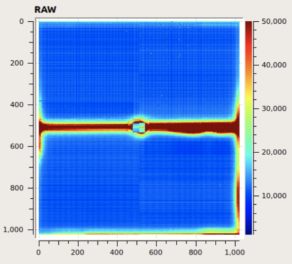
Fig. 9.4 If the light in the hutch or some LEDs are ON, or if the P_CCD_Low and Stage3 gauges are ON while the pnCCD is up and running, you will see something like this image, where a bright intense band covers the middle of the detector. Find out which light source produces this light and turn it OFF.
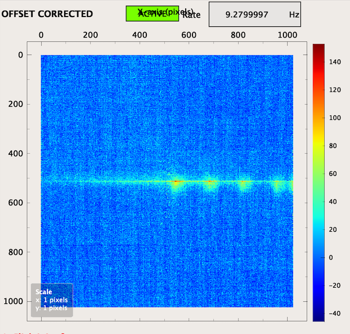
Fig. 9.5 Example of the light produced by an encoder (from the motion system) on the pnCCD detector. These intense blobs are usually slowly moving to the left or right when an encoder is ON while the detector is operating.
If the light in the middle of the detector looks like Fig. 9.6, this is the stray light from the scattered FEL beam from the slits, etc. You cannot do anything about it. The SQS beamline scientists will attempt to reduce it as much as possible but some amount may still be there.
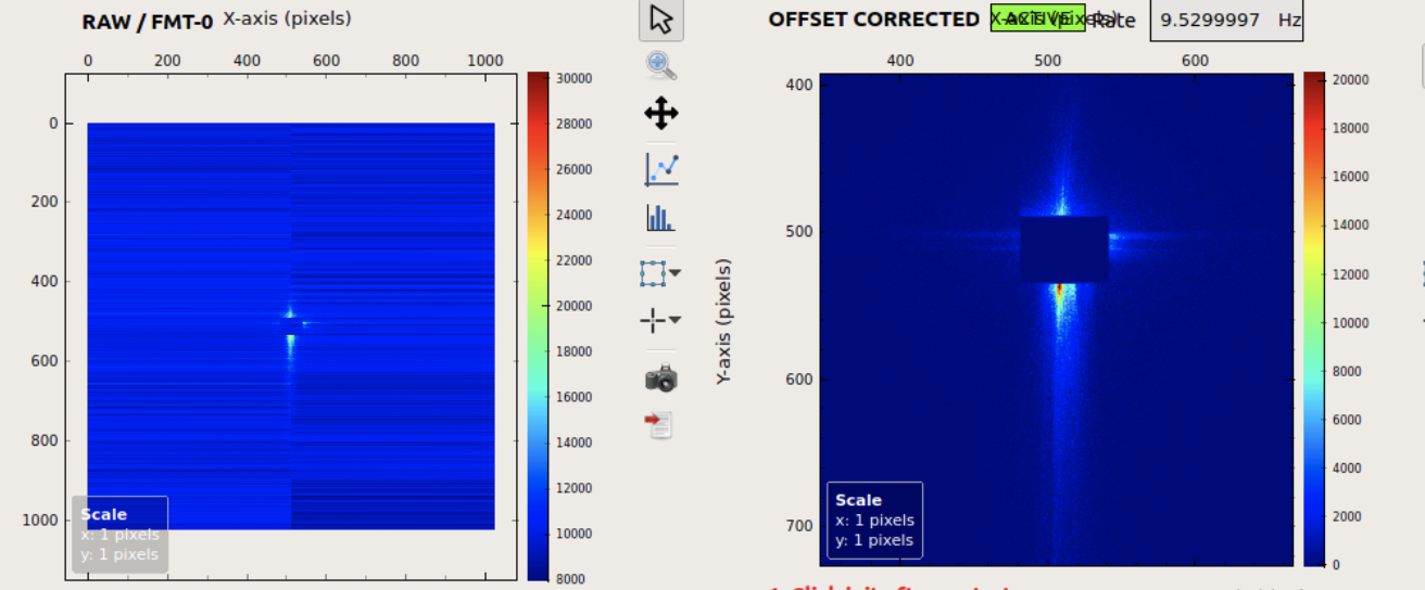
Fig. 9.6 Example of the stray light on the pnCCD detector.
9.10. When Is Annealing Necessary?
If during the FEL beam tuning, one or two pnCCD sensors are too close to the beam, or the beam is badly tuned and is not in its correct spot, it may hit the detector. This is dangerous and should be avoided at all cost. Kill the beam immediately. Depending on the damage caused, you may require to:
- stop the experiment and power cycle the detector. Wait for at least 15 minutes after the detector is OFF and before you turn it back ON again.
- stop the experiment and anneal the detector immediately. This is the worst case scenario. In this case, it is best if Robert Hartmann from PNSensor is contacted first.
- go on with the experiment until the beamtime is over on that day and then anneal the detector for a few hours before the start of the next shift.
To know whether or not the detector has to be annealed:
- Stop the experiment after the detector was hit by the FEL beam.
- Ask the SQS to close the necessary valves and turn off the necessary gauges and lights so that you can take a dark run.
- Take a couple of dark runs: one with gain 1 and one with the same gain as the one used beforehand.
- Process both dark runs (see
DarkRuns).- Open the reports of both these dark runs, as well as those of the most recent dark runs with the same gains taken previously (preferably on that same day).
- Take a look at the common mode corrected noise maps for all these dark runs and compare the ones from dark runs after the incident and those from the dark runs before the incident.
- The normal expected noise levels of pnCCD are given in Table 8.3 for each gain. If the new common mode corrected noise maps for the dark runs taken after the incident are too much (2 times or more) higher than these values AND those of the dark runs taken on the same day (and with the same gain) before the incident, it would be best to anneal the detector over the next few hours after this shift is over.
See EndofShift for the instruction on how to anneal the pnCCD.
Note
- The pnCCD noise level (in ADU) is quite low for gains 1/16, 1/64, 1/256, 1/340 and 1/512. You may not even notice the bright spot caused by the FEL beam hitting the pnCCD detector directly if the current gain is among these. So, to assess the damage, change the gain to 1 and take a dark run to analyze it.
- If the detector is damaged due to the FEL beam direct interaction or if the intensity of the beam is too high and the detector has been exposed to the high intensity beam for too long, you will see an afterglow on the detector, i.e., even after the beam is stopped and taken away and when the beamline is dark, the raw and corrected images still show a bright hot spot, stripe, etc. on some regions of the detector which may be damaged. Pay attention and avoid this situation. Again, depending on the gain, you may not notice these effects. Always change the gain to 1 to be able to assess the severity of the situation.
- The bottom pnCCD sensor may show an afterglow due to some unknown effects. This is usually triggered if the detector is exposed to high intensity beams for a long time (hours on end). If this is interfering with the experiment, annealing may be necessary to get rid of this afterglow effect.
9.11. Problems with the pnCCD Motion System
If there are any problems with the pnCCD motion system, notify the SQS members so that they can resolve the issue.
9.12. Problems with the pnCCD Vacuum System
9.12.1. Turbo Pumps and/or Valves Are in Error State
If there are any problems with the pnCCD vacuum system, notify the SQS members so that they can resolve the issue.
9.12.2. The Cold Cathode Gauge is Showing \(10^{-10}\) mbar
This is because this gauge is OFF. Do not turn it ON while the pnCCD is running and is in use as it will interfere with the experiment by producing a lot of noise on the detector. Once it is turned ON when possible, it takes a minute or two to start reading an accurate pressure inside the pnCCD chamber.
9.12.3. The Interlock Is Tripped When Cold Heads’ Heaters Are Turned ON
Turning OFF the pnCCD chillers and turning ON the heaters for the cold heads may cause the pressure in the pnCCD chamber to go up too much triggering the local interlock on the pnCCD chamber. To open valve \(V_{2}\) to start pumping on the chamber again:
- Re-enable the channel 2 sensor’s relay.
- Shutdown valve \(V_{2}\) Karabo device (see
KaraboDevicesVacuum) and then reinstantiate it.- Reset the Karabo device and then open the valve again.
9.13. The Bottom pnCCD Module Is Not Cold Enough
If the Normal operation mode is selected, the pnCCD outputs approximately 14 W of heat. Because of this and because the thermal coupling between the bottom detector module and its corresponding cold head is not very efficient, the temperature on the bottom pnCCD module cannot be regulated and stabilized efficiently. In this mode of operation, the bottom module is normally a few degrees hotter than the top module. To try to lower this temperature difference, set the top module temperature setpoint at \(-30\) degC while that of the bottom module should be set to \(-40\) degC. Even then, the bottom module may be stabilized at \(-27\) degC or so.
9.14. Problems with the DAQ Syatem
In general, if the DAQ problem at hand could not be solved following the solutions recommended here, call DOC/ITDM.
9.14.1. Data Are Not Saved Properly
Make sure the correct data sources are selected on the SQS_RUN_CONTROL_GLOBAL_STATE scene (see RunControl).
Also, Check the status message window of the SQS_RUN_CONTROL_GLOBAL_STATE scene and make sure there are no errors there. Also, check the Karabo devices related to the data aggregators (see dataAggregatorDevices). Those related to the data sources you are trying to use should be up and running and be in Active state. If not, call Controls OCD or DOC.
9.14.2. Data Aggregators Are in Error State
Call DOC/Controls OCD.
9.14.3. Applying Configuration in the Run Controller Fails
Try again but slowly. After each step, wait until the action is confirmed in the status message window of the SQS_RUN_CONTROL_GLOBAL_STATE scene and no errors are spotted. Check the Karabo devices related to the data aggregators (see dataAggregatorDevices). Those related to the data sources you are trying to use should be up and running and be in Active state. If the problem still exists, call DOC/ITDM.
9.14.4. The Proposal Number in the Run Controller Is Not Recognized
If the proposal number you are trying to use is correct, check the Meta Data Catalog. Browse to the General menu tab and check the Beamtime status. If it is Finished (Beamtime), the proposal is closed and you cannot add any more runs to it. Your only choice is to use a different proposal. If the Beamtime status is Active, contact ITDM.
9.15. The pnCCD Is Not Sensitive to the FEL
If the raw and corrected images are not responding to the FEL beam and the beam has no issues and the FastADC digitizers are not having any other known issues (see ADCTroubleshooting), the problem could be that the trigger cables on the sequencer are swapped. To fix this issue:
- Stop the FastADCs acquisition from the
pnCCD_Mainscene.- Stop the sequencer and quit by typing
Qon the sequencer console.- Carefully, follow the instructions given in
SequencerCableConnectionto correctly connect the trigger cables to the sequencer.
This problem should now be solved. You can restart the sequencer (see SequencerCTRL) and restart the FastADCs acquisition from the pnCCD_Main scene.
9.16. The Sequencer Shows Only One Running Counter Instead of Two
If as shown on Fig. 9.7, the sequencer shows only one running counter on its console instead of two, the trigger cables on the sequencer are swapped. To fix this issue:
- Stop the FastADCs acquisition from the
pnCCD_Mainscene.- Stop the sequencer and quit by typing
Qon the sequencer console.- Carefully, follow the instructions given in
SequencerCableConnectionto correctly connect the trigger cables to the sequencer.
This problem should now be solved. You can restart the sequencer (see SequencerCTRL) and restart the FastADCs acquisition from the pnCCD_Main scene.
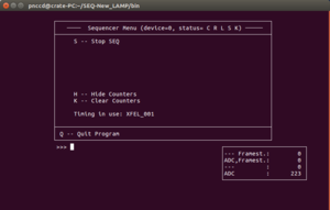
Fig. 9.7 If the trigger cables on the sequencer are swapped, the sequencer will only have one counter running as shown here.
9.17. Problems with Karabo Bridge
If you have issues with the Karabo bridge, make sure the SQS_DIGITIZER-UTC1 data source is selected. If this is the case and the problem still exists, call DOC/Controls OCD and contact the DA OCD.
Footnotes
| [1] | A software device written by Steffen Hauf (European XFEL employee) which converts the digitizers’ data to the raw image observed on the pnCCD_Acquisition scene in Karabo. |