Running the Device
No special action should be taken by the user to instantiate the device; this is done automatically by the Karabo system.
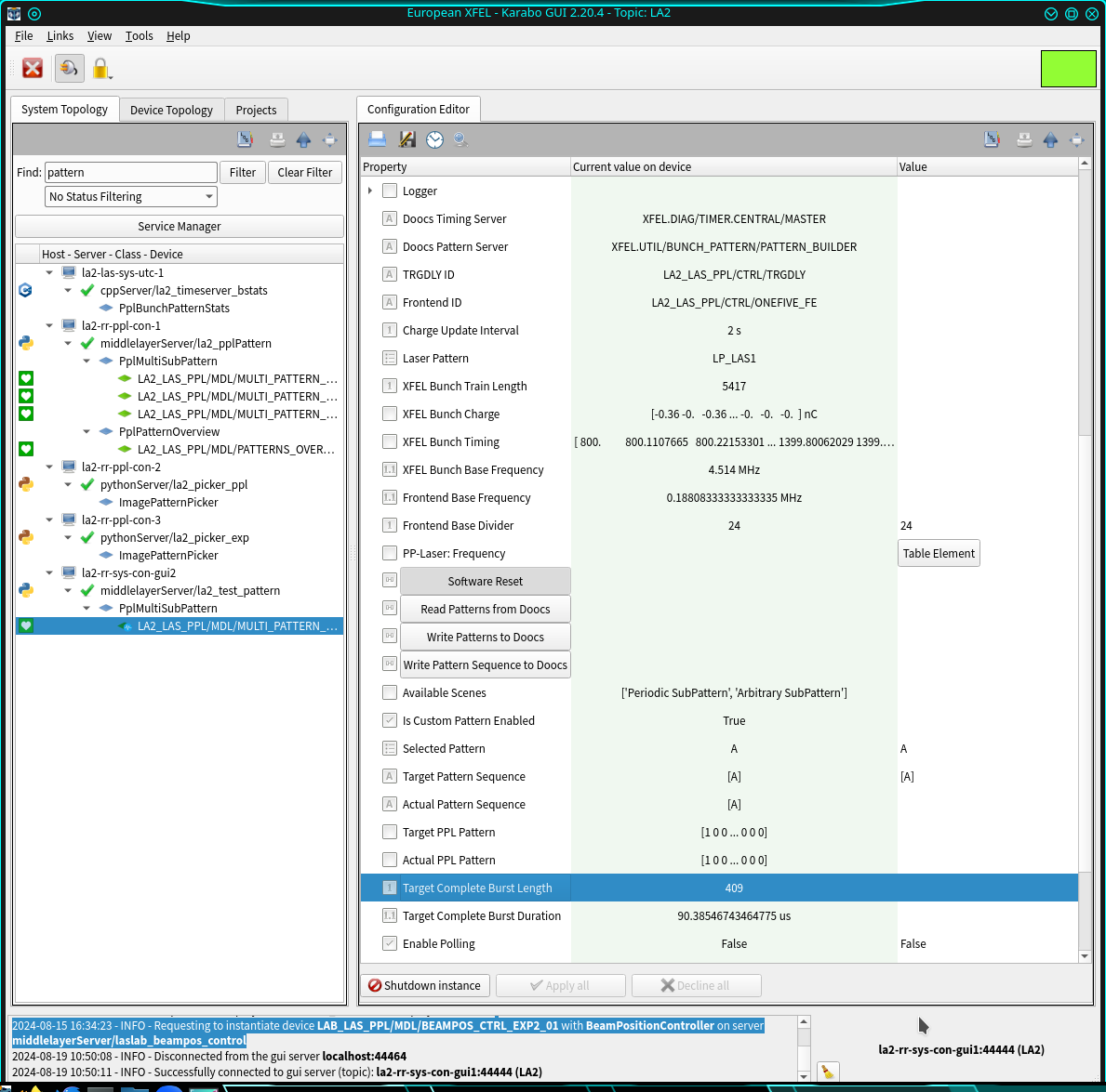
An example of the device configuration editor after it comes online, is presented in Fig. 1:

Fig. 1 Fig. 1: After successful initialization the users can visualize the PPL pattern they are allowed to work with.
After initialization the users can cross-check the correctness of the PPL bit in use:
Laser Pattern: The laser pattern which can be used by an instrument. Every pattern corresponds to a specific bit in the 32-bits pattern associated to each electron bunch. One instrument user should have only one pattern, except LAS group which can instead modify two bits for testing purposes. The pattern bits available in the system are the following:
– LP_LAS1: For LAS,
– LP_LAS2: For LAS,
– LP_SPB: For SPB instrument,
– LP_FXE: For FXE instrument,
– LP_SQS: For SQS instrument,
– LP_SCS: For SCS instrument,
– LP_SASE2: For SASE2 instruments.
The status of electron bunches in the XFEL machine is periodically retrieved. The interval to wait before polling for an update from DOOCS can be tuned by changing the value of the parameter Charge Update Interval (its default value is 2s). Each instrument will have visualized only the sequence of bunches emitting X-rays in their corresponding SASE tunnel. In case of LAS or Control user, at moment only SASE1 is displayed; in the next releases the possibility to choose at run time which tunnel to monitor will be given. The base frequency for the bunches (XFEL Bunch Base Frequency) is regularly updated from DOOCS.
The variable Selected Pattern allows to configure the ppl patterns in a train. At the moment, up to eight types of train configurations can be set, named as A, B, …, H, which can be selected via its drop-down menu.
A train configuration can be repeated N times in sequence by configuring the variable Target Pattern Sequence. Pattern types not inserted in the sequence will not be used in the PPL firing sequence. The currently running sequence is shown in the variable Actual Pattern Sequence. Let us suppose we have configured, as an example, the target configuration N[A]M[B]. This will translate in firing the PPL in sequence the pattern A for N consequent trains, and soon after firing the pattern B for the next M trains. At the end of the last train, the sequence will restart from the beginning. In order to make the target sequence active (i.e. to save it in DOOCS), the slot Write Pattern Sequence to Doocs has to be called.
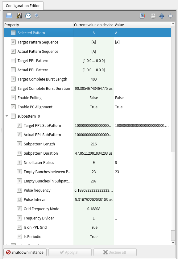
Each train can be then configured with up to four consequent subpatterns, independently configurable, exposed as nodes in the device configuration editor, Fig. 2.
For each node (sub-pattern) the following variables can be set:
Nr. of Laser Pulses: The number of laser pulses in a sequence;
Frequency Divider: The integer to select a submultiple of the base frequence generated by the the laser frontend (FE) hardware. The pulse frequency and the interval between pulses in the specific sequence will change accordingly.
The frontend base frequency Base FE Frequency is determined by a frequency divider internal to the hardware, whose value change is always notified to the pattern device, and shown in the property Frontend Base Divider; the latter is not shown directly in the scene to avoid accidental changes of this critical variable.
When the frontend divider changes the target pattern is not modifed, while the pattern divider is recalculated according to the newly received frontend divider and the pulse frequency in the target pattern. In case this pulse frequency results no more to be a submultiple of the frontend frequency the divider is defaulted to unity, and a notification is shown to the users via the device status property displayed in the device scene in a ‘Text Log’ widget.
Everytime the frontend divider changes in the device its value is saved online, and can be retrieved after device restart in case the connection with the frontend hardware cannot be established via Karabo. In this scenario LAS users can also change its value according to a new configuration set in the frontend hardware, thus allowing building laser patterns consistent with the pulse frequency set in the frontend hardware (referred to as ‘pattern being on the PPL grid’).
When the frontend divider changes in the pattern device a new lookup table PP-Laser: Frequency of allowed pulse frequency values is generated. The table is compiled only up to the first 44 frequency divider values, and its aim is to help the user visualizing the pattern properties.
After each selection (Laser Pulses or Frequency Divider) is entered in the subpattern editor, the variable Target Ppl Pattern will be updated. The total subpattern length (in unit of XFEL bunches) and interval, including all empty bunches, will be also updated. In case of subpatterns made only of empty bunches the subpattern length is given by the number of hypotetical inter-pulse empty bunches (allowed by the chosen divider value) plus one unit (the missing initial pulse). This configuration will not be automatically transferred to the DOOCS server; this will be done only after pressing the slot (button) Write Pattern to Doocs. The new pattern stored in DOOCS (Doocs: Ppl SubPattern) will be then updated accordingly. Note that the patterns saved in DOOCS are regularly monitored every ten seconds if the Boolean property “Enable Polling” is set; it is by default True for devices with instrument PPL bit, False with LAS1/LAS2 bits.
Each time a pattern or a pattern sequence is pushed to DOOCS the proper duration for the PPL Pockels cell is calculated, to let the correct number of pulses propagate to the instrument; its trigger is configured accordingly for allowing this. The value is displayed in the device status property and is shown in the device scene. If needed, this behaviour can be disabled by unsetting the Boolean property Enable PC Alignment.
To retrieve the current patterns the slot Read Pattern from Doocs can be called. An automatic readout from DOOCS is done soon after patterns have been pushed to DOOCS.
The variable Target Complete Burst Duration shows (for each selected pattern type) the duration of the corresponding complete PPL burst, from the first to the last pulse.
