The Graphical User Interface (GUI)
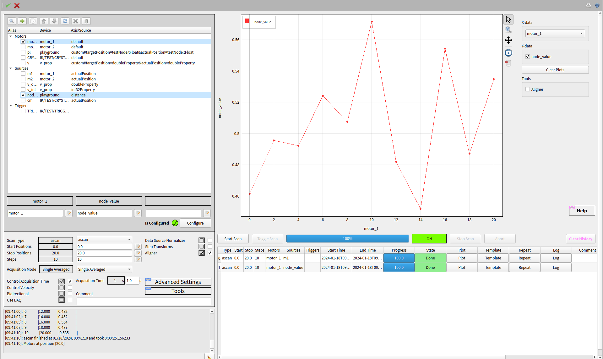
Fig. 2 Main Karabacon scene.
Karabacon scene is devided in several areas:
Device environment
Scan settings
Scan control (start, toggle scan, stop and abort), history table and logging
Real-time and historical plots
Device environment
The device tree represents the scan tool device environment. A new device can be added by dragging a device name from the system topology or project view to the tree view. If the device name is dropped on the top level item Motors, Sources or Triggers then a new children entry is added. If it is dropped on the device item then the deviceId is updated.
Note
Device alias has to be unique and can contain letters a-z, A-Z, numbers: 0-9,
and special characters: .-:/_. White spaces are not allowed.
Setting duplicated aliases will set the scantool to error state.
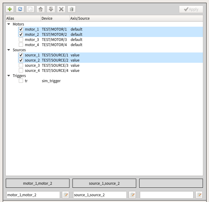
Fig. 3 Device environment tree and widgets to select device aliases.
After changing the device tree one has to click Apply button to approve the changes. Above the tree a toolbar with buttons to add, sort, copy, move and delete devices is available. By clicking on the Add new devices a dialog to add new devices is shown. The dialog lists all devices from the topology, allows filtering by text and allows to add devices to the selected device group.
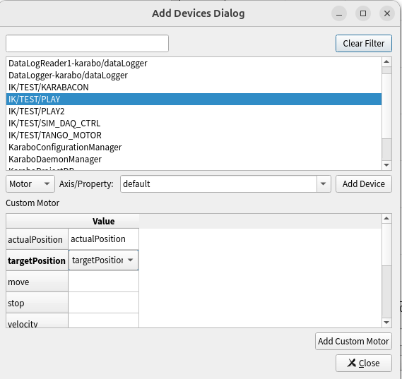
Fig. 4 Dialog allowing to add new devices to the device environment.
The dialog contains the following GUI components:
List with available Karabo devices.
Filter text field to filter available devices.
Combo box to select device type and Axis/Property field to define the motor axis or source property.
Table to define new custom motor interface.
To add a new device, select the device type (Motor, Source, or Trigger), then either double-click the device ID or click the Add Device button. To add a custom motor, select the device ID, complete the necessary table fields, and click the Add Custom Motor button
Tip
For a quick device selection type the requested aliases (comma separated and without whitespaces) in the text fields of the currently selected aliases.
After all devices have been selected the device environment can be configured. Please click the Configure button and the karabacon will establish the connection to all devices, check if they are in a proper condition and have been configured properly with a correct axis. You only need to re-configure if you changed the device selection. Please note, that configuring the DAQ might take over a minute!
Scan settings
If the configuration of the scan environment was successful, the isConfigured boolean is set to True and the applied configuration is displayed in the status box. If the configuration is not successul, the status box will briefly describe what happened wrong. After successful configuration the scans can be launched with the selected parameters and settings.
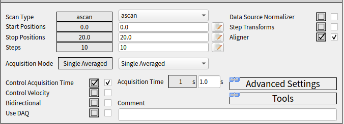
Fig. 5 Scan settings.
Note
The Scan Environment has to be always configured when new devices are selected for the scan.
Note
The Scan Environment must not be configured for scan parameters (start, stop, steps etc.) only.
Scan control and history
The following scan control buttons are available:
Start Scan: starts the configured scan.
Toggle Scan: pauses or resumes the current scan.
Stop Scan: stops the currently running scan.
Abort: stops the currently running scan. The stop slot of motors and triggers is called.
Clear History: clears the history table.
The history table keeps track of all executed scans. It is possible to plot scan results (Plot), repeate a scan (Repeate) and configure the scantool based on the historical scan settings (Template). During a scan these commands are disabled. The history table has a limited number of rows. You can adjust it by changing history.cacheSize.

Fig. 6 The scan history table with a scan being executed.

Fig. 7 Scan history with executed scans.
Real time and historical plots
The Karabo scan widget is a custom plot widget, for dedicated use with the scantool. Most importantly, it detects 1D and 2D scans and adjusts it’s layout accordingly. It also offers basic analysis features, like selecting between multiple datasource c hannel(s) and displayed axis coordinates.
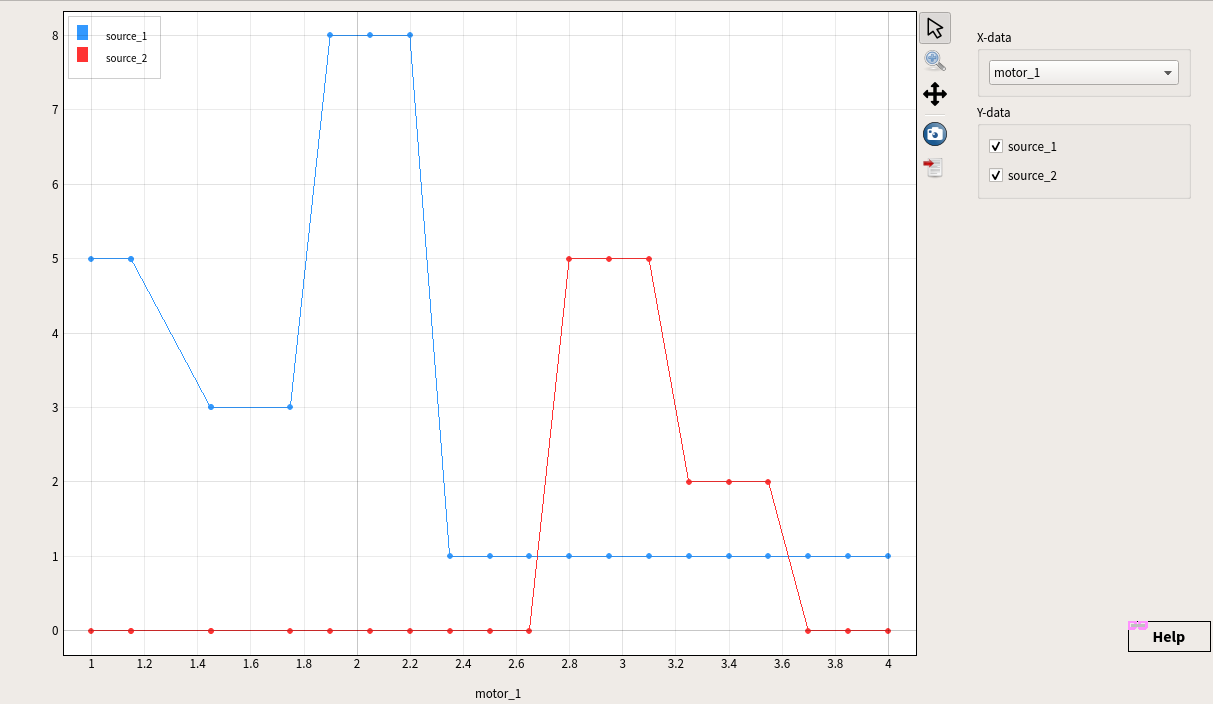
Fig. 8 One dimensional plot.
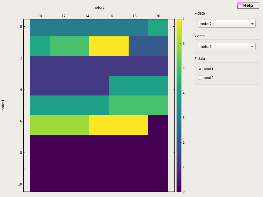
Fig. 9 Two dimensional plot.
Tip
Double clicking on the plot will move motor(s) to the corresponding position(s).