General
The AGIPD system is located in the MID hutch. More information about the detector itself you can find in this paper from February 2024:Operational experience with Adaptive Gain Integrating Pixel Detectors at European XFEL
Recording data with the agipd detector requires the surrounding infrastructure:
- a vacuum system to pump the detector vessel
- a cooling systems for the electronic boards outside the vacuum as well as the FEMs in the vessel.
- power supplies
- interlock system to ensure the detector is only cooled when the vessel is pumped and only powered up completely when it is cold.
- DAQ system
- Online preview and
- Clock and Control system
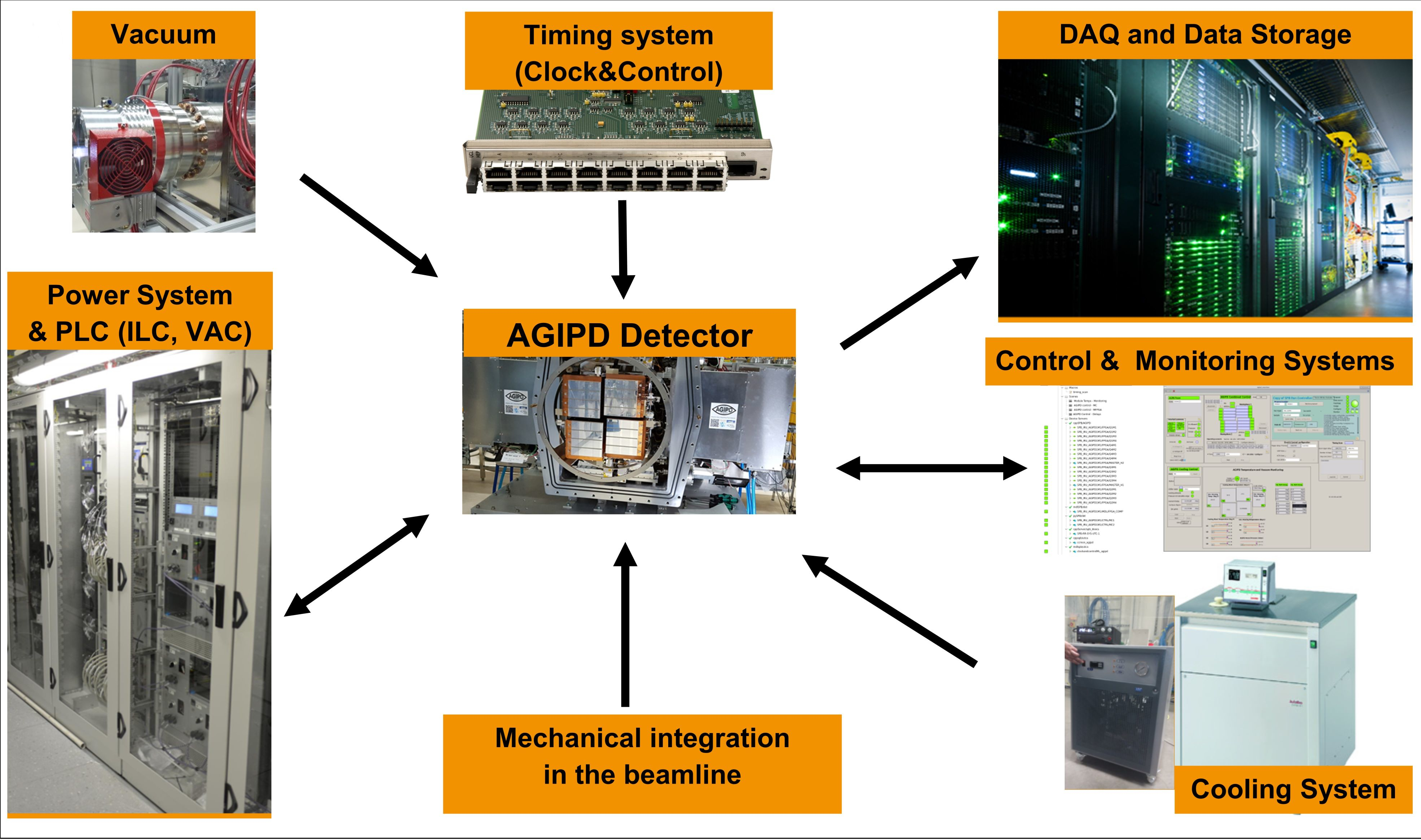
Fig. 1 Overview of the infrastructure needed for the AGIPD-1M system.
This manual will not cover the infrastructure completely, please also refer to corresponding manuals for more information if necessary (the following list makes no claim to being complete!):
- Mpod power supplies for low and high voltage of the detector: https://docs.xfel.eu/share/page/site/agipd/document-details?nodeRef=workspace://SpacesStore/3dfffbe2-8c2f-43ee-a629-28f916cd2056
- Karabo: https://rtd.xfel.eu/docs/karabo/en/latest/index.html
- Julabo Chiller (in-vacuum cooling): https://docs.xfel.eu/share/page/site/agipd/document-details?nodeRef=workspace://SpacesStore/939da9fd-ee4b-4ecb-a990-7481f7467c3e
- Huber Unichiller (cooling of the electronics in the wings): https://docs.xfel.eu/share/page/site/agipd/document-details?nodeRef=workspace://SpacesStore/208b1865-70cc-40de-85ed-a6ee40a18f59
- Clock & Control: https://docs.xfel.eu/alfresco/webdav/Sites/advancedElectronics/documentLibrary/FPGA/Clock%20and%20Control/clockControlProject.pdf
- Online Preview: https://rtd.xfel.eu/docs/calng/en/latest/
The detector should only be operated by instructed personnel. Users should not operate the detector directly at all or just do very basic things like starting and ending a run. The control system for the detector is still under development, but it allows the operator to control and monitor the most critical parameters (temperatures, pressures, voltages currents, etc..) and do the steps necessary for standard operation with some exceptions (e.g. Huber chiller for cooling of the wings).
The interlock kicks in at a pressure of 1 :math: * 10^-3 mbar. This means that the detector HV will be switched off and the detector will be warmed up.
ELOG
There is an electronic logbook for the MID-AGIPD detector: https://in.xfel.eu/elog/1+MPix+AGIPD+Detector+for+MID/
Everything done with the detector should be documented there. If you do not have access, but will use the detector, please ask Jola or Natascha for access rights.
Naming convention
The AGIPD detector has two separate hemispheres, which are in principle controlled independently. Hemisphere 1 consists of Quadrants 1 and 2 and hemisphere 2 of Quadrants 3 and 4 with modules QXm1 -QXm4 for each quadrant (see Fig. 2). Figure Fig. 2 shows the naming convention used for AGIPD detector. This convention should be used in all control systems to identify geometrical position of the detector single modules.
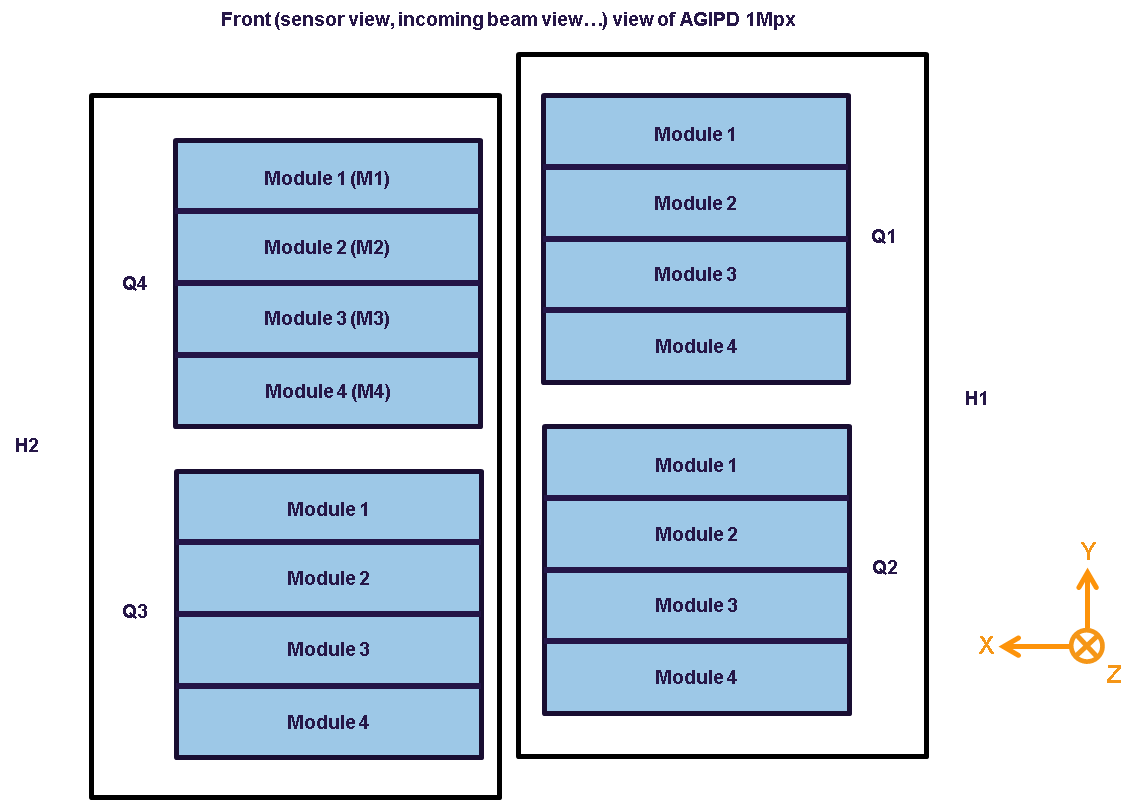
Fig. 2 The naming convention for the AGIPD-1M system. Coordinate Z is the beam direction.
Note
Some control names which come from the “copy” of AGIPD Tango names are still in the different notation. It is mainly for control devices for microcontrollers (i.e. MC1 and MC2)
Below is the name conversion of the AGIPD modules from “CFEL-like”: m1-m8 to “XFEL-like”: QiMi
- wing 1 (h1)
m1 –> Q2M4
m2 –> Q2M3
m3 –> Q2M2
m4 –> Q2M1
m5 –> Q1M4
m6 –> Q1M3
m7 –> Q1M2
m8 –> Q1M1
- wing 2 (h2)
m1 –> Q4M1
m2 –> Q4M2
m3 –> Q4M3
m4 –> Q4M4
m5 –> Q3M1
m6 –> Q3M2
m7 –> Q3M3
m8 –> Q3M4
Figure Fig. 3 shows the preview of the 16 modules including the xfel notation of the modules and the corresponding daq nodes and HV channels.

Fig. 3 Preview of the modules, including the xfel notation and daq nodes/ HV channels.
Rules for AGIPD detector operation at MID
General
- The general rules for MID also apply to detector operators.
- Users are not allowed to operate the detector, users are all persons who have not received a proper training on detector operation
- Any intervention shall be reduced to the absolute minimum not to endanger data taking and the quality of scientific data during the beam time
- Any modifications of detector configuration or/and operating parameters is not allowed without prior consultation of one of the following persons: run coordinator, Roman or Jola
Technical (for AGIPD operators on shift)
- Information about the configuration will be given to Run coordinator. An example can be seen in Fig. 4.
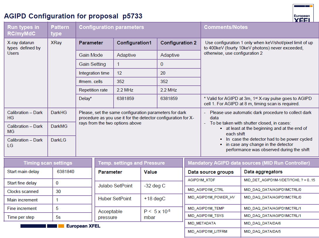
Fig. 4 Example of how the the configuration table might look like. The given Data sources are mandatory for processing the raw data later on. Always check the latest version in the hutch!
- ..note ::
- For MID the Trigger delay might vary with the distance of the detector from the sample and should be adjusted & confirmed with a timing scan if the detector is moved during the beam time.
- Dark runs for high, medium and low gains (~50s per gain) should be taken by the operator:
- at least twice during the shift: at the beginning and at the end of shift
- in case detector was power cycled
- there is any indication that performance of the detector changed or could change
- Before power cycle the detector, please make sure that it is really needed:
- check if DAQ is OK
- check if control systems are OK
- After power cycling the detector, please run detector in monitoring mode (do not store the data) at least for 20 min. It takes time before the temperatures on detector are stabilized.
At the beginning of the shift
Refer to the section Starting the AGIPD Detector at MID for details and explanation
- Locate the printout with the configuration and operating scenarios (Fig. 4).
- Check the Huber chiller on the roof of the Hutch: is it working, is the setpoint at the value that is displayed on the printout?
- Check, whether the Julabo chiller shows warning 40
- Start Karabo Gui if not open.
- Check the vacuum pressure (in the agipd_overview_scene): is the pressure value below what is displayed as acceptable pressure printout?.
- Check the state of the Julabo chiller (in the agipd_overview_scene): is the Setpoint of the Julabo chiller at the correct value (again the printout)?
- Does the state of DAQ and preview look ok (no errors, crosses, red indicators)?
- Are Electronics and Asics of the detector powered? If not: power up.
- Check preview for the state of the modules (compare to the printout above the screens, Fig. 3 )-> Is it Ok?
- Power High Voltage
- Take dark runs (use the dark data procedure in the main overview scene)
At the end of the shift
- Take dark data (one run for each gain setting)
- Stop data taking
- Power down HV of the detector
- Check, whether the Julabo chiller shows warning 40