Calibration
To overcome the difficulty in measuring the incident angle \(\phi\) of the primary beams, the following method is applied.
By shifting the mirror stage in the optical delay line, Fig. 4, a delay \(\Delta t\) is added between the two input pulses, resulting in a shift \(\Delta Z_0\) of the center of SH transverse distribution
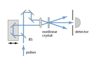
Fig. 4 Setup of an intensity autocorrelator. BS refers to the beam splitter.
Combining equations on transverse profile \(D_z\) with shift \(\Delta Z_0\) the dependence on the intersection angle \(\phi\) is removed, and the pulse duration can be obtained as
The ratio \(K = \frac{\Delta t}{\Delta Z}\) is a calibration factor which allows the conversion of the SH transverse profile (measured in pixel units) to the pulse time profile (measured in femtosecond units).
Its determination with sufficient accuracy is challenging. To overcome this difficulty the following procedure is applied. One of the two optical paths can be varied by pulling or pushing one mirror in the line in a controllable way using a micrometer. A change \(\Delta l\) of the micrometer head position results in a pulse delay of \(\Delta t = 2\Delta l / c\) and in the shift \(\Delta Z_0\). Thus, shifting the SH distribution, as measured in the CCD camera, in two extreme opposite positions (1 & 2) of the sensitive area allows the measurements of calibration factor with a lower relative uncertainty as shown in the steps below:
Considering the above expression of \(\tau_p\),
resulting in
This way, the calibration factor \(K = (\frac{2}{c} \cdot \frac{\Delta l_1 - \Delta l_2}{\Delta Z_1 - \Delta Z_2}) [\frac{fs}{pxl}]\) can be calculated with a larger relative precision using a reproducible and controllable procedure.
It should be noted that the multiplying factor 1/2 in the above equation results from the initial and non-realistic assumption of a rectangular time profile and uniform transverse intensity profile for the incoming beams. More realistic models for the unknown time shape of initial pulses should be considered. Assuming the Gaussian and hyperbolic secant shapes for the pulse time-profile results in the factors 1/2 and 1/1.54, respectively.
The oscillator pulse duration is then calculated as the mean value of these extracted values, and the contribution from model uncertainty to the global systematical uncertainty can be estimated as half of the maximum deviation between the two calculated values.
The above mentioned calibration steps are handled by the device configuration editor. The user should take care to properly select the fitting region reducing the contribution from the fundamental beams. The fitting window can be optimized configuring the keys Fit Lower Limit and Fit Upper Limit. Also, attention should be taken in order not to cut the profile tail of the SH beam thus affecting the measurement of the FWHM.
After moving the generated SH beam to one side of the sensitive area of the CCD camera (by properly translating the mirror stage in the optical delay line with the micrometer), by clicking on Current Image as 1st Calibration the current values of peak position and FWHM will be set as Image1 Peak (x) and Image1 FWHM (x), respectively. Similarly, the second set of calibration parameters are obtained steering the SH profile in the other side of the camera and clicking on Current Image as 2nd Calibration.
Once the two calibration images are acquired, the calibration constant \(K\) can be calculated by clicking on Calibrate after setting
- Delay Unit to \(\mu m\);
- Delay to the entire translation of the mirror stage, equivalent to \((\Delta l_1 - \Delta l_2)\). This measurement should be taken by the user;
or, in case the optical delay between the two calibration images was provided already in femtosecond unit, after setting
- Delay Unit to \(fs\);
- Delay to the time delay.
The extracted Calibration constant allows to calculate the pulse duration from the measured FWHM \(D_z\),
\(\alpha\) being the multiplication factor originating from the model assumed for the time-profile of the pulse.
The uncertainty of the pulse duration is preliminary estimated via error propagation by the uncertainty on the fit FWHM, assuming the uncertainty of the calibration constant is negligible and that no correlation between the fit parameters exists.