Introduction
The AutoCorrelator device is designed to provide an online determination of the pulse duration using a single-shot auto correlator [1].
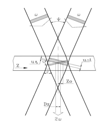
The measurement of the time profile of pulses is based on the following principle, graphically displayed in Fig. 1. The input beam is sent to a beam-splitter; the two identical beams propagate along two distinct optical paths until they intersect in a non-linear crystal. Here, due to the high-intensity of the beams, a second harmonic beam (SH) is created and its integrated energy is measured by a CCD camera located after the crystal.

Fig. 1 The diagram describes geometrically the intersection of two identical beams in a crystal and the generation of the second harmonic beam.
The pulse duration of laser pulses can be determined upon measuring the transverse distribution of the energy deposited in the CCD camera. From geometrical considerations in Fig. 1, assuming for the incoming beams a rectangular time profile \(\tau_p\) and uniform transverse intensity profile, it is found that the transverse profile \(D_z\) of the second harmonic depends on the pulse duration \(\tau_p\) of the fundamental beams,
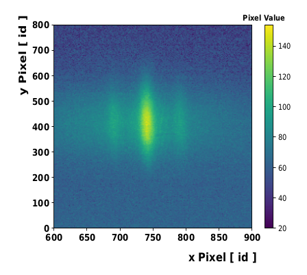
where \(u = c/n\) and \(\phi\) are the speed of light and the intersection angle of input beams, respectively, in the crystal with refractive index \(n\). The transverse profile \(D_z\) is determined from the data accumulated with the CCD camera available in the system. An example of camera image is presented in Fig. 2:

Fig. 2 The fundamental beams and the second harmonic beam are detected in the CCD camera located after the non-linear crystal.
The figure shows clearly the deposited energy from the signal of the generated second harmonic beam (central and more intense peak) and of the two fundamental beams (low intensity side signals). The transverse profile \(D_z\) is determined as FWHM from the fit to the SH peak.
The angle \(\phi\) cannot be measured with sufficient precision for a reliable extraction of pulse duration \(\tau_p\). The way used in the device to determine the pulse duration from the measured transverse profile is presented the calibration section.
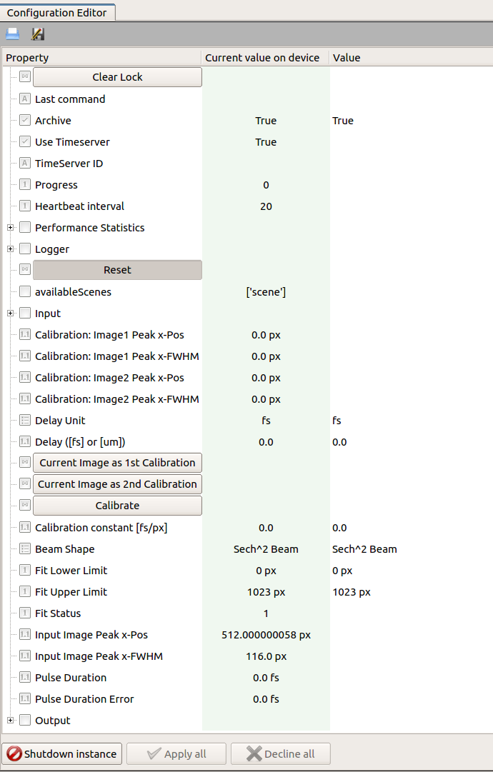
The device configuration editor is presented in Fig. 3,
The camera device providing the image of the beam profile should be set in the key input.connectedOutputChannels of the autocorrelator device. For each camera image the projection along the x-axis is calculated, a fit is performed according to a selectable model (Beam Shape) for the time-profile of the pulse, and the peak position and FWHM are determined from the fitting function (Input Image Peak x-Pos and Input Image Peak x-Pos). The Fit Error parameter is an integer flag describing the fit status. If it is equal to 1, 2, 3 or 4, the solution was found, otherwise the solution was not found [2]. The possible fit status values are:
- 0: Improper input parameters were entered,
- 1: The solution converged,
- 2: The number of calls to function has reached default max number,
- 3: Max for relative error is too small, no further improvement in the approximate solution is possible,
- 4: The iteration is not making good progress, as measured by the improvement from the last five Jacobian evaluations,
- 5: The iteration is not making good progress, as measured by the improvement from the last ten iterations,
- ‘unknown’: “An error occurred.
The result of pulse duration is presented only in case of a solution is found, and the fit status value is lower than four.
| [1] | RP Photonics Encyclopedia, https://www.rp-photonics.com/autocorrelators.html |
| [2] | Scipy.org, https://github.com/scipy/scipy/blob/master/scipy/optimize/minpack.py |
