Trigger Parameters
At run time the trigger accessed by the middlelayer device can be configured by setting its parameters: Fig. 7:
Delay: The trigger delay in nanosecond units with respect to the reference timing in XFEL. A warning is issued if the value is larger than 0.1 s, as you might be off by a train;
Pico-Delay: A finer tuning of the trigger delay, in picosecond units. To help the user, the device shows also the calculated total trigger delay currently set (“Total Delay”);
Duration: The trigger duration (or “width”) in nanosecond units. The maximum train frequency (“Max Train Freq.”) allowed by this value is automatically calculated as
\[f = 1000 / \Delta T \ \ \ \ \ MHz\]
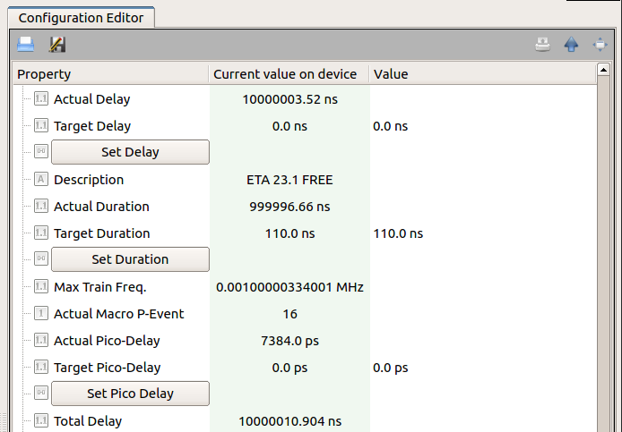
Fig. 7 The trigger time parameters can be configured at run-time.
Note that x2Timer device configures the trigger timing parameters using, as defined in DOOCS, multiples of the base step 9.23 or 923 for nanoseconds or picoseconds, respectively. Differently from that method, the middlelayer device x2TimerML allows the user to easily choose a parameter in terms of real time units. In case the selected value was not an exact multiple of the base step, a rounding to the closest multiple is done.
As usual in many karabo devices, a parameter is described by its actual value (e.g., Actual Delay) and by the value which the user is interested in (e.g., Target Delay). To set the desired value of a trigger parameter the corresponding slot (e.g., Set Delay) has to be eventually clicked.
The karabo middlelayer is exposing to the users some of the trigger parameters configurable directly in the DOOCS system, and by changing these parameters, the trigger configuration is actually changed in DOOCS. An example of the DOOCS panel comprising the timing parameters of a trigger channel is presented in Fig. 8,
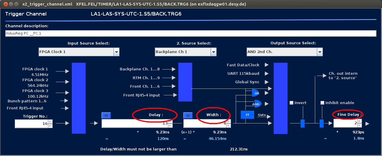
Fig. 8 Doocs panel to configure a specific trigger output channel in a μTCA board.
An interesting feature of the device is the possibility to allow pulse on demand triggers; a trigger is output when a pulse condition is generated. This is achieved by setting a logical “and” condition between the configurable μTCA trigger handled by the device and a second configured trigger channel, “2. Source Select” in Fig. 8. In the karabo device this is done by setting to True the boolean Use Conditional Trigger, Fig. 9, enabling this variable the Conditional Trigger Mask will be set, generating the above mentioned logical and condition. Please, check with EEE experts before changing this mask.
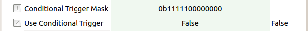
Fig. 9 Out of the initial 10 Hz triggers, the user can select the ones corresponding to specific conditions, for example in pulse on demand situations.
The device provides the user with some useful features which might be used in case of a scan of the trigger delay, Fig. 10. A step value (Step Size) can be defined, and the delay can be increased (decreased) of one step unit using the slot StepUp (StepDown). The coarse and fine delay values will be set according to the closest multiple of a basic step. The size of the step value can be doubled or halved using the slots Step x2 or Step /2, respectively.
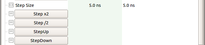
Fig. 10 Scan capabilities are provided allowing to modify the trigger delay by predefined steps.