3. Hardware Setup
3.1. Overview
FastCCD is a 2-D imaging detector. It can be run in Full-Frame mode (FF, 2 Megapixel, up to 60 Hz) and in Frame-Store mode (FS, 1 Megapixel, up to 120 Hz). Currently, the camera is operated always in FF mode.
The detector has been developed at Lawrence Berkeley National Laboratory in the U.S. and has been delivered with a DAQ rack.
As the intensity of the European XFEL beam on the detector may be very high, a central hole for the beam to pass through is required. This hole, 1.8-mm in diameter, was laser-drilled after the sensor was fabricated, bonded and tested.
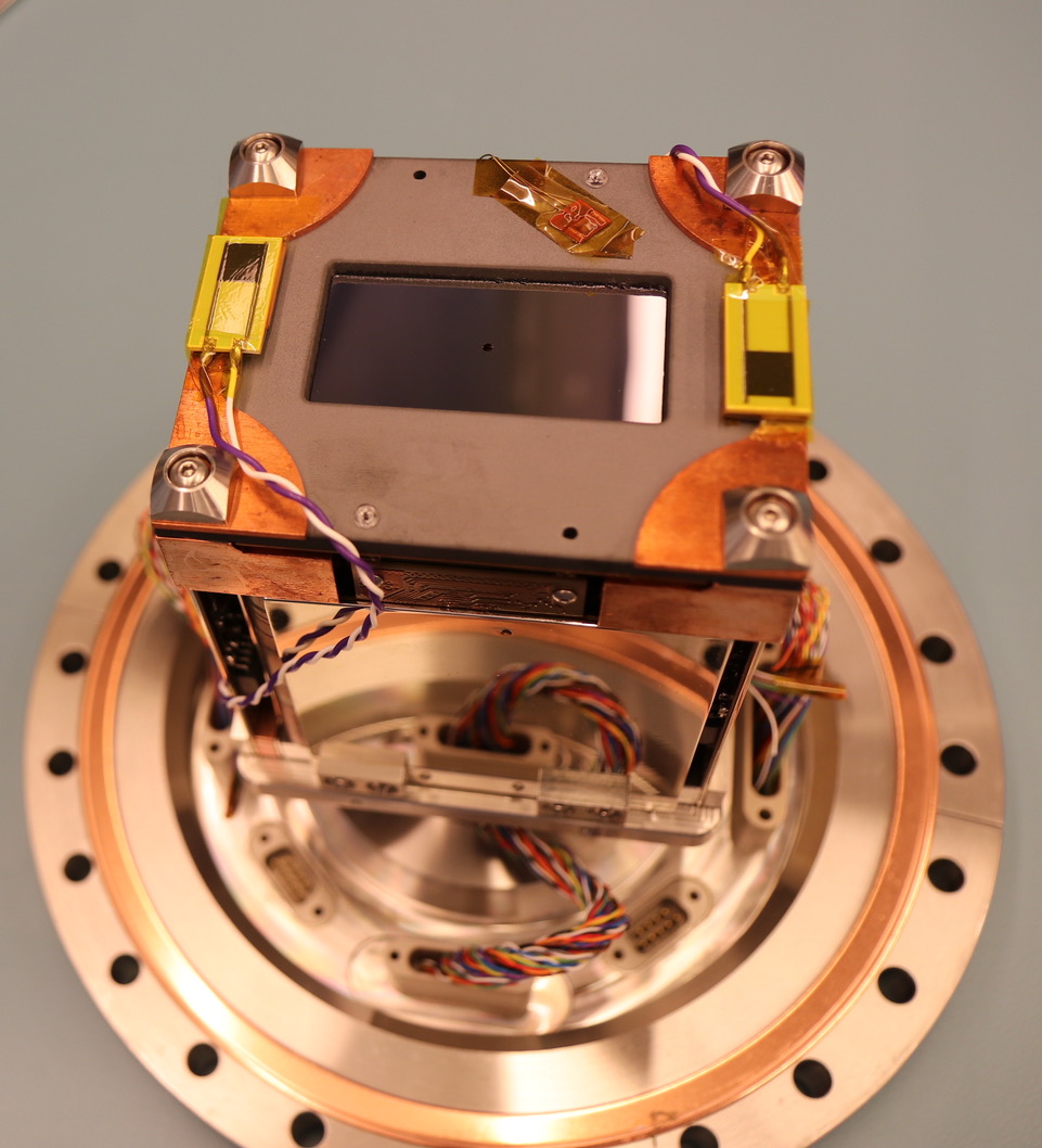
The main components of the system are an in-vacuum camera head shown in Fig. 3.1, a camera interface electronics board, and an Advanced Telecommunications Computing Architecture (ATCA) based readout and data processing subsystem.
More information on the performance of the detector can be found in arXiv:1612.03605 [physics.ins-det]
| Property | Value |
| Pixel size | 30 μm × 30 μm |
| Sensor thickness | 200 μm |
| Dynamic range | \(10^3\) above 0.5 keV |
| Sensor size | 1920 × 960 pixels |
| Photon energy range | 0.25-6 keV |
| Beam hole size | 1.8 mm |
| Quantum efficiency | \(\geq94\%\) for Eγ >1 keV |
| Speed | 60 fps (FF), 120 fps (FS) |
3.2. The Detector
The primary components of the detector include: the camera head with all in-vacuum modules, a vacuum-to-air interface, the backend readout electronics, and auxiliary components like temperature controller, chiller, and power supply.
3.3. Readout and Control Electronics
The FastCCD electronics is hosted in a mobile rack that contains:
an ATCA crate with:
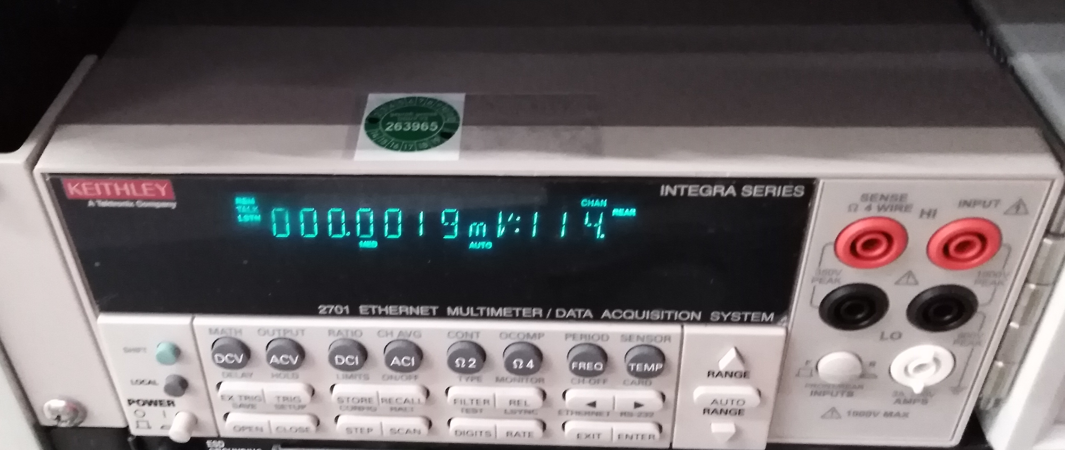
a Keithley digital Multimeter (see Fig. 3.8)
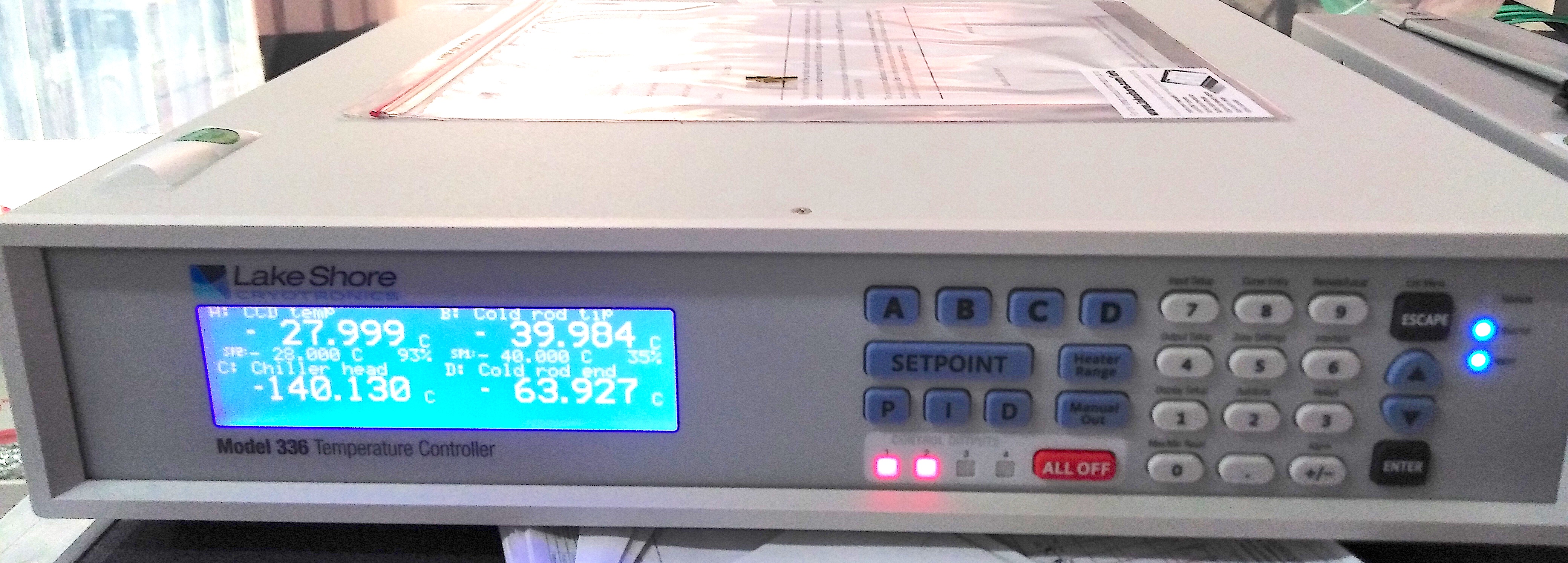
a Lakeshore temperature control unit (see Fig. 3.9)
an uninterruptible power supply (see Fig. 3.10)
an Acopian power supply for the camera electronics with a web controlled switch (see Fig. 3.11)
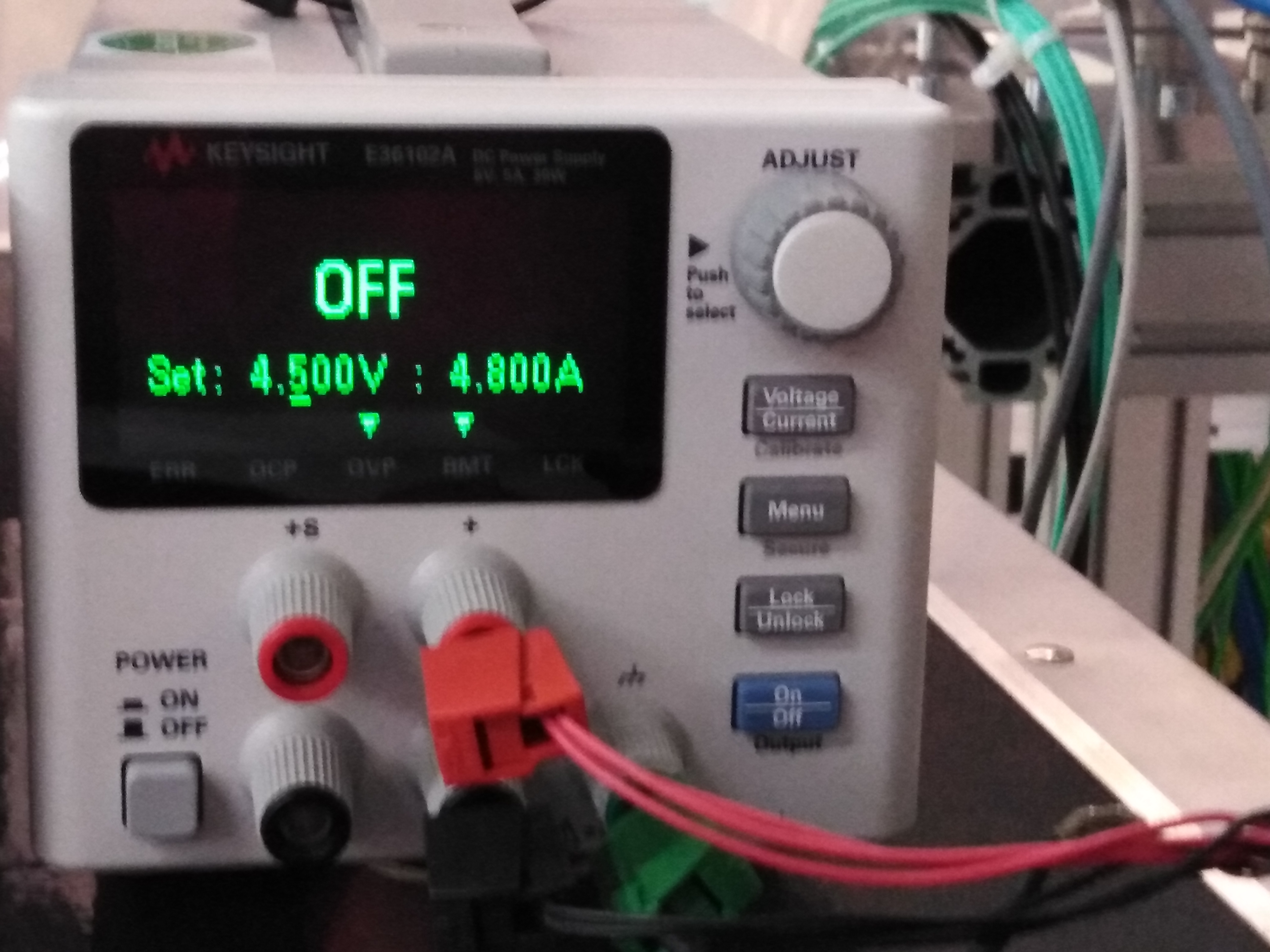
a Keysight power supply for the fiber optics transceivers (see Fig. 3.12)

Fig. 3.6 The Camera Interface Node (CIN) module is the one where cyan fiber optics cables are connected.

Fig. 3.7 The black lever on the right of the module (1) can slide upward to power cycle the CIN. The handle underneath (2) will pop out during this process and needs to be pushed in to be able to restart the module’s power.

Fig. 3.11 The Acopian power supply. The LEDs on the right side must all be ON (green) when this power supply is ON.
3.3.1. The Camera Interface Node
The Camera Interface Node (CIN) is an ATCA module connected to the camera head via 6 fiber optics channels (see Fig. 3.6 and Fig. 3.7). It provides the control signals for the camera, and reads out and de-scrambles the acquired frames.
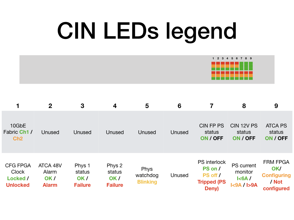
The CIN has a number of LEDs on its front panel that can be used to infer the status of the device.
3.4. Cooling System
The detector requires cooling during operation to prevent overheating.
3.4.1. Chiller Setup
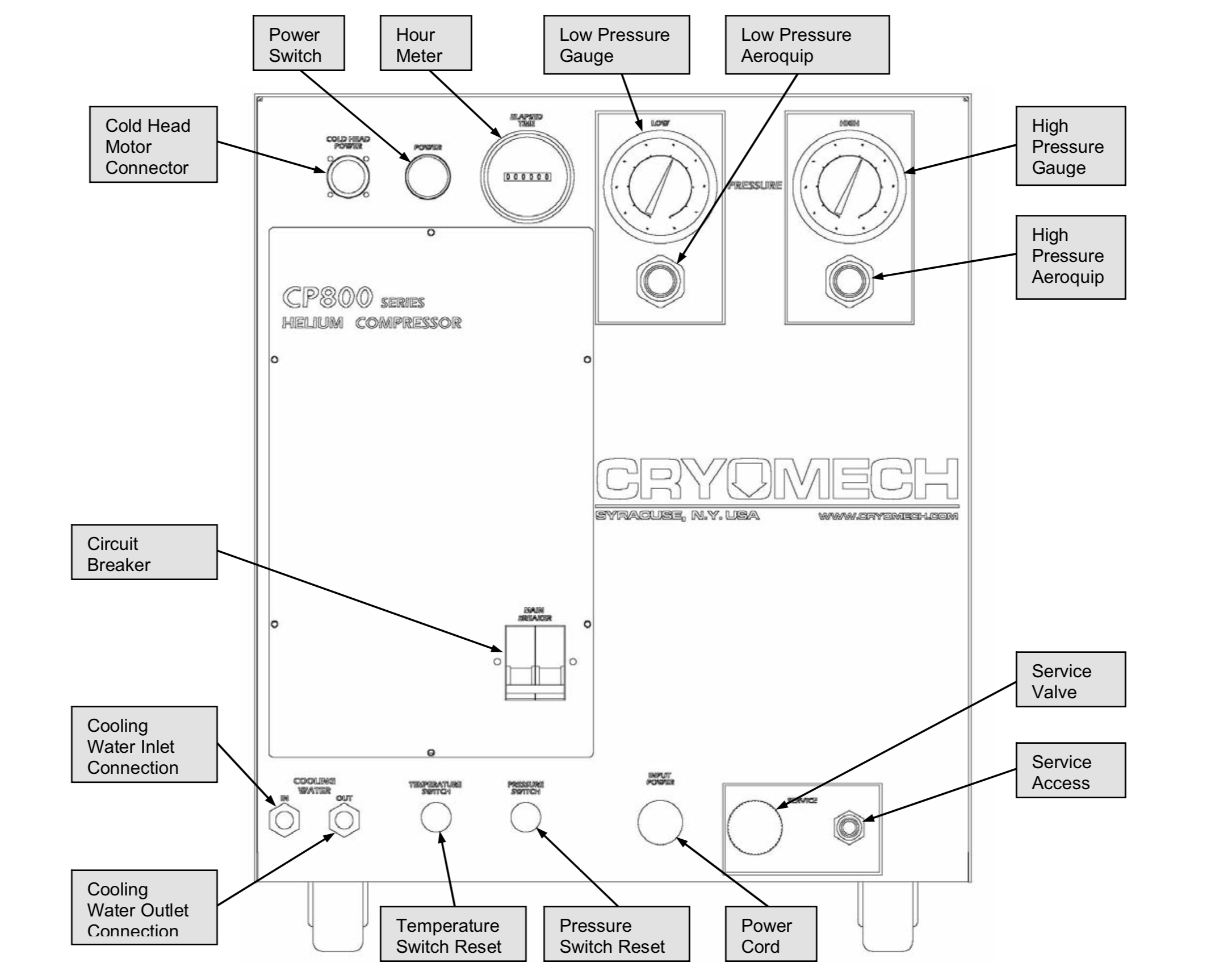
The CRYOMECH CP830 cryo-chiller is located near the electronics rack. Follow these instructions to turn it on (if you encounter problems, refer to the troubleshooting section):
make sure that the power is connected and the interlock allows the chiller operation. If this is the case, the red LED on the chiller’s front panel (under interlock connector) is on (see Fig. 3.14 and Fig. 3.15).
make sure the cooling water valve is open, the valves are on the wall, under one of the network patch panels, look for a green valve marked FastCCD:
- open the green valve marked FastCCD.
- turn the red valve to the right of the green valve anti-clockwise all the way.
close the circuit breaker (up position is closed) on the chiller front panel.
press the large green button on the front panel, the button will lighten up.
the red LED on the back panel (see Fig. 3.16) should turn on and the chiller should make a regular (~1Hz) loud ‘chick’ noise. If it does not, it means that the compressor is not working (check the troubleshooting section).
the FastCCD temperature should start decreasing after ~1/2 hour.
allow for ~3h for the temperature to go down to -28 degC.
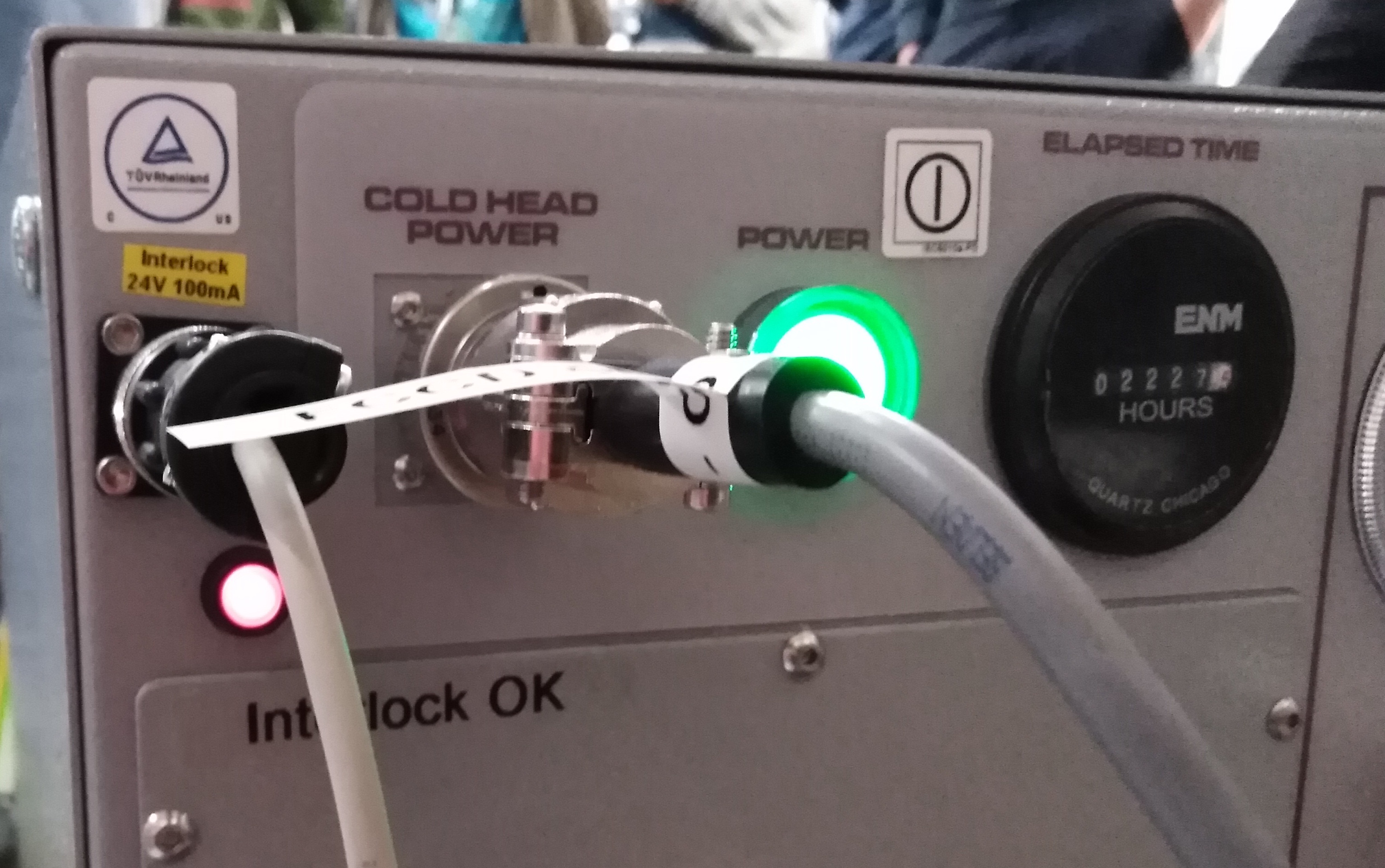
Fig. 3.15 If the power to the chiller is connected and the interlock allows the chiller operation, the red LED on the chiller’s front panel (under interlock connector) is on.
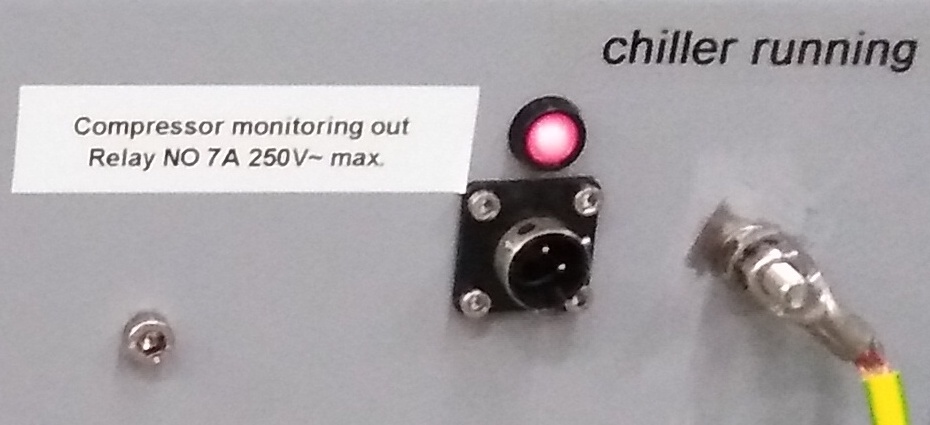
Fig. 3.16 The back panel of the FastCCD chiller. The red LED should be on if the compressor is ON and you should hear the chiller’s distinguishable chick noise.
Danger
Do not turn the detector off and leave the chiller on unless you have set the Lakeshore according to Section 6.2.
3.4.2. Chiller Shutdown
Follow these instructions to turn the chiller off:
- press the large green button on the front panel.
- the chiller should fall silent and the green light goes off.
- Open the circuit breaker by lowering the handle on the chiller front panel.
The chiller can also be turned off from the Interlock scene. However, in this case, there is no feedback other than the temperature starting to rise.
3.5. Lakeshore Temperature Controller
The temperature of the camera is kept stable by two heating resistors (Ohmite 5 W each) installed next to the CCD plane. A PT-100 temperature sensor is installed on the same support.
An additional 100-W heating cartridge is installed near the tip of the copper rod, close to the camera (see Fig. 3.1). A PT-100 is also installed there. This second heater is required to counterbalance the cooling power provided by the Chiller.
The resistors are controlled by a Lakeshore 336 unit, which powers them in a closed feedback loop with a PT-100 in order to reach a specified temperature.
Note
The Lakeshore 336 has several heater settings 0: Off, 1: Low, 2: Medium, 3: High. You should only ever use the High setting (3).
This means that there are three sources of heat in the system:
- FastCCD itself (0 W when off, ~20 W when on but unbiased, ~30 W when the CCD is biased and the detector is acquiring at 10 Hz)
- the CCD heater (0-10 W)
- the rod heater (1-100 W)
Depending on the camera status and desired CCD temperature, the rod heater needs to be set following the table in Section 6.2.
Note
For safety reasons, the Lakeshore unit will turn off all heating loops if the CCD temperature or the rod temperature exceed 20 degC.
The Lakeshore also provides an alarm signal that will disable the camera power supplies if the CCD temperature is above 0 degC, and disable the chiller if the CCD temperature falls below -60 degC.
3.5.1. Interlock
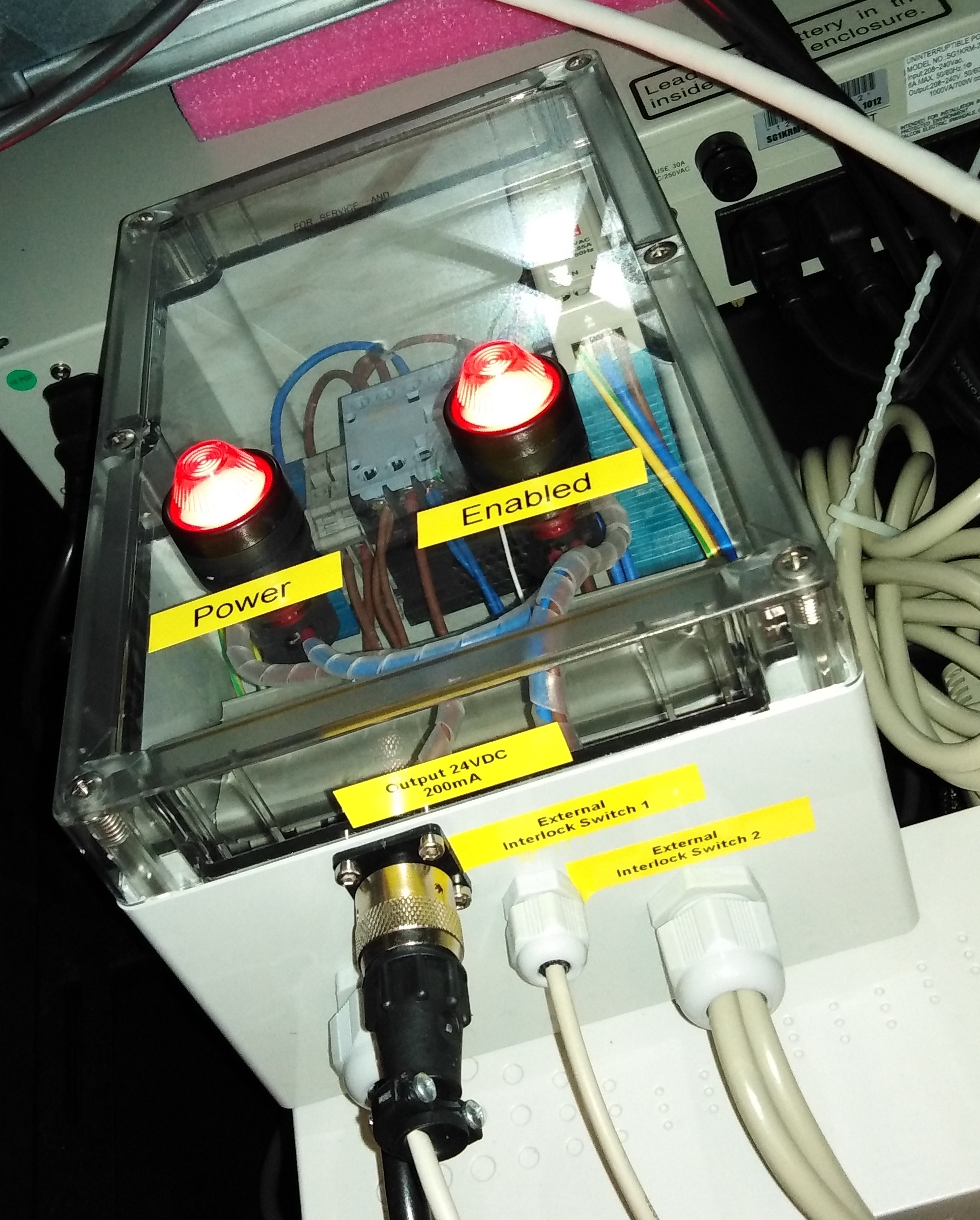
A hardware interlock box is connected to the Lakeshore relay output (see Fig. 3.19). It is designed to cut the power to the two power supplies (camera head and fiber optics transceivers) in case the camera head’s temperature exceeds 0 degC.
A second Lakeshore relay output will cut the chiller power if the camera temperature falls below -60 degC.
