7. Troubleshooting
7.1. Camera Control
7.1.1. The Detector Control Device Is in ERROR State
Make sure you have read Section 4.3.3.
The most likely cause of an ERROR state is that the “Exception in slot Fiber status update”. This happens when the detector power supply is completely off and the karabo device is complaining that it cannot check its status.
This can happen when one of the following is true:
the power is disabled via karabo (power enable “on/off” button on the Interlock scene)
the interlock has disabled it because one of the following conditions is true
- the pressure in the vessel is too high
- a vacuum pump has failed
- the Lakeshore high temperature alarm is on
You can check these in the Interlock scene. You can also check by looking at the interlock box in the FastCCD crate (if one light is off then the power is cut off). Finally you can see if the screen of the Keysight power supply on the FastCCD rack is completely black.
To solve this, remove the error condition:
- make sure that the FastCCD pressure is below 1e-3 mbar
- make sure that the temperature is below 0 degC and reset the alarm on the Lakeshore. To do that you can use the button in the Interlock scene or press the “alarm” button on the front panel of the Lakeshore itself and answer “yes”
- press the power enable button on the Control scene
Then press the “reset” button on the Control scene to force the device to try and connect to the power supply again.
7.1.2. Cannot Turn the Camera On
The Camera On and Main Power On buttons are greyed out if the CCD temperature or vessel pressure are outside the allowed range (see Section 4.2.1).
If the device is in ERROR check that if the Lakeshore alarm is on (see Section 7.3.3). The power supply is automatically turned off if the temperature or pressure are outside the allowed range. Again check the Interlock scene to make sure you are in the correct configuration and that you have acknowledged the Lakeshore alarms.
7.1.3. Repeated FAILURE Uploading Bias File
Danger
If you operate the camera with the wrong bias voltage settings, you may damage the CCD.
If all of the readout values for the Bias voltages differ from their reference values check if the camera Acopian power supply is physically turned off. Check the voltage provided by the power supply using the Status scene. Check that the button is pressed and that all LEDs are on. The power supply is located at the bottom of the electronics crate and has several red LEDs on the front panel.
7.1.4. Cannot Turn the Bias Voltage On
The bias voltage cannot be turned on if the CCD temperature or vessel pressure is outside the allowed range (see Section 4.2.1). Check the Interlock scene to make sure you are in the correct configuration.
7.1.5. Excessive Current Draw by Detector
The currents drawn by the detector head can spike when turning the bias voltage on and off. Sporadic errors are of no concern but if you get frequent messages it may be a sign that the beam intensity on the CCD is too high. Reduce the signal intensity and contact an expert if the issue does not go away.
7.2. Data Acquisition
7.2.1. Raw Data Preview Is Not Being Updated
Here is a list of possible causes and solutions.
- The frames are all very similar
- Check if the Frame Number is being updated. If it is, then maybe the frames are just all very similar. Adjust the color scale and zoom into the preview picture.
- The external trigger selection has not been confirmed
- Once you switch to External_1 trigger mode you need to hit RETURN, the DAQ status should then change to ACQUIRING.
- The Karabo DAQ device is not connected to the detector
- press the “Reconnect” button in the DAQ section of the Control scene.
- The camera is off or not properly configured
- Check the Status messages and make sure the camera is on and that it is properly configured. If you are unsure, turn it off and follow the start procedure again.
7.2.2. Raw Data Preview Has Some Odd Features
Here is a list of possible causes and solutions.
- The raw data is a test pattern
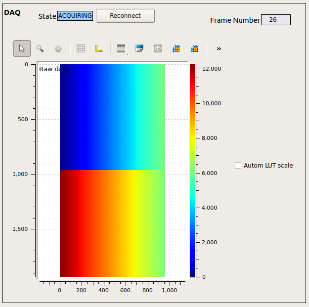
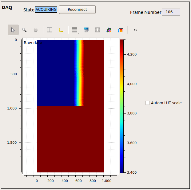
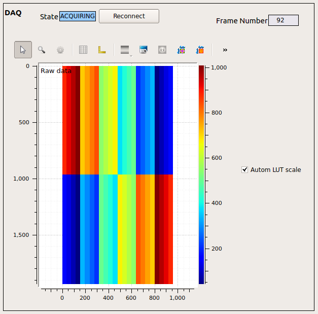
- If, after resetting the color scale, the raw preview looks like Fig. 7.3, it means that the Fiber Optics test pattern is on; you can turn the FO test pattern off using the “FO pattern off” button in the FCCD control device. If the preview looks like figures Fig. 7.1 or Fig. 7.2, it means that the fCRICs are not configured correctly; turn the triggers off and send the fCRIC configuration file again.
- There is a big blob in the middle of the preview
- The Alignment Laser (ALas) may be hitting the CCD. Check if the instrument scientists are using the laser and if it is supposed to go through the CCD.

Fig. 7.1 The fCRICS test pattern visible in the raw preview. You will see this if the fCRICs have not been configured correctly.
7.2.3. Electronic Noise Visible But No X-Ray Signal
If the CCD temperature is already below -30 degC when you turn the bias voltage on, the electronics might be too cold to react. If it happens, turn the bias off, let the system warm up and try to turn the bias on again.
7.2.3.1. Problems with Saved Data
7.2.4. Cannot Connect to the Maxwell Cluster
If you are trying to connect from one of the desktops in the control room you will have to login to exflgateway first. If you are outside the DESY/XFEL network (for instance, your laptop is connected to the WiFi network) you will have to go trough bastion.desy.de).
7.2.5. No or Corrupted Data Are Being Written to File
- You are using the software trigger
- You are using the software trigger. Do not use the “start/stop triggering exposures” button, rather make sure the software trigger is off and set the trigger to “external_1”. See also Section 4.2.4.1.
- Connection between DAQ device and Data Aggregator lost
This may happen if the FastCCD DAQ device is restarted when the DAQ is not in ignore mode. You can ask ITDM on-call to verify the status of the TCP connection between
SCS_CDIDET_FCCD2M/DAQ/FCCD(onexflcon145) and its Data Aggregator.To solve the problem:
Switch the trigger mode to Internal
Go in ignore mode
Ask ITDM to
- Shut down the Data Aggregator (for FCCD it should be SCS_DAQ_DATA/DA/5).
- Shut down the FCCD DAQ device (
SCS_CDIDET_FCCD2M/DAQ/FCCD). - Shut down the cppServer/scs_fccd_daq server and all its children.
- The cppServer/scs_fccd_daq server should restart itself almost immediately.
- Wait for at least 90 seconds after the server restarted. Then restart the Data Aggregator.
- Restart the FCCD DAQ device.
Push data to DAQ:
- make sure the proposal number is correct, if not, change it and retrieve the proposal.
- Apply Configuration.
- Monitor Data.
- Change trigger mode to External_1.
Take a test run, if you still have issues, ask ITDM to check the connection again.
7.3. Hardware
The most common issues and solutions are listed here. For more information on troubleshooting an issue with the chiller, refer to the troubleshooting section of the chiller manual
7.3.1. Chiller Does Not Turn On
Here is a list of possible causes and solutions.
- The chiller has no power
- Connect the power cable to the outlet. Check that the circuit breaker on the front panel is up (closed).
- The chiller is interlocked
If the red LED on the chiller front panel is off, then the chiller is interlocked (see also Section 3.5.1). Check the Interlock scene in karabo to find out what is causing the issue:
- CCD temperature below treshold
- See Section 7.3.3
- Pressure over threshold or turbo pump error
- Wait for pressure to fall below 1e-3 mbar.
- Chiller disabled in karabo
- Enable the chiller in the Interlock scene in karabo.
- The chiller has overheated
this usually happens if the cooling water was off. Follow these instructions to recover:
- make sure the cooling water is flowing (touch the pipes to feel the water temperature).
- wait ~15 minutes.
- press the over-temperature reset switch at the bottom of the fron panel.
- try to turn on the chiller again.
7.3.2. The Chiller Head Is Not Making a Regular (~1Hz) Loud ‘Chick’ Noise
Here is a list of possible causes and solutions.
- the power cable from the motor to the head is not connected
- check that it is connected on both sides.
- the pins in the chiller connector have receded
- Get a qualified electrician to disconnect the power plug, open the chiller and push the pins back in place.
7.3.3. CCD or Rod Temperature Does Not Rise
This can happen if:
- the heater range is set to anything other than 3
- Change the heater range to 3.
- The Lakeshore alarm is on
- See the next session.
7.3.4. The Lakeshore Alarm Is On
The Lakeshore 336 continuously monitors the CCD temperature and will go in an Alarm state if the temperature goes above 0 degC or below -60 degC. In the first case, it will disable the camera power supply; and in the second case it will disable the chiller.
The Lakeshore will keep the relevant equipment disabled until the condition that caused the alarm is removed (the temperature has to go back into the allowed range) and the alarm is acknowledged. You can do the latter from the Interlock scene or manually from the front panel of the Lakeshore.
7.3.4.1. Additional Safety Measures
The Lakeshore will automatically disable a heater if the temperature measured by the corresponding sensor is above ~20 degC. This leaves you enough room to use the Lakeshore to quickly warm up the detector if needed but avoid going above room temperature.

