Operation
This section highlights the balic principle of operation of a JUNGFRAU module.
Turning on and off
Cooling
Each module of JUNGFRAU needs cooling to dissipate the heat generated by the FEM and the JUNGFRAU readout board, for a total of about 36 W. Without cooling in place, the modules will heat up, operation parameters like the sensor current will not be stable, increasing the difficulty of the measurements. Moreover, there is the chance of damaging the electronics with an inefficient heat dissipation. Therefore, before powering up the modules, cooling system must be turned on, and its correct functioning verified.
For modules in air, a set temperature above the dew point is suggested, in order to avoid possible condensation on sensitive electronic components: any temperature between 15 \(^{\circ}C\) and 20 \(^{\circ}C\) is suitable.
For the reasons explained above, operation without proper cooling is strongly not recommended.
Power
A module is powered by applying a Low Voltage value of +12 V through the dedicated connector on the JUNGFRAU board. This will turn on the board and the ASICs in the FEM. An average JUNGFRAU module draws a current in the range of 2.5 - 3.5 A, but during the power up it can briefly reach higher values: therefore, a current limitation of 5 A per module (if there are more modules in series) is suggested.
After a few seconds from the power up, the current should stabilize and the module is on. To control its operation from Karabo GUI, two devices are needed:
- a RECEIVER per module;
- a CONTROL device.
These two devices must be turned on in this order (after the module is powered): first all the RECEIVERS, then the CONTROL.
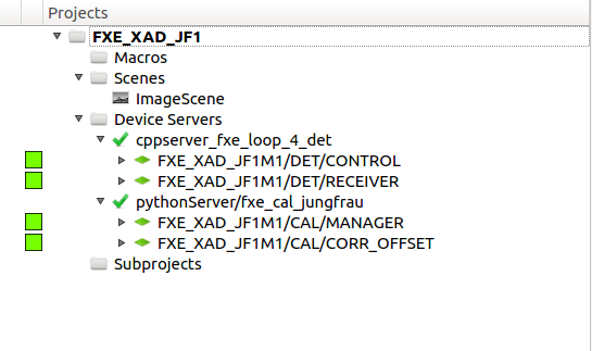
Fig. 11 Detail of the JUNGFRAU Project at FXE; the RECEIVER and CONTROL devices can be seen, both active
High voltage to the sensor can be supplied in two ways:
- if the JUNGFRAU board of the module in use has an internal voltage divider board (see Fig. 12), HV can be applied via CONTROL; it will not applied until the CONTROL device is first instantiated and in that case the default value of the HighVoltage parameter (see Basic operation settings: CONTROL device) will be applied;
- otherwise, HV must be applied externally by a power supply.
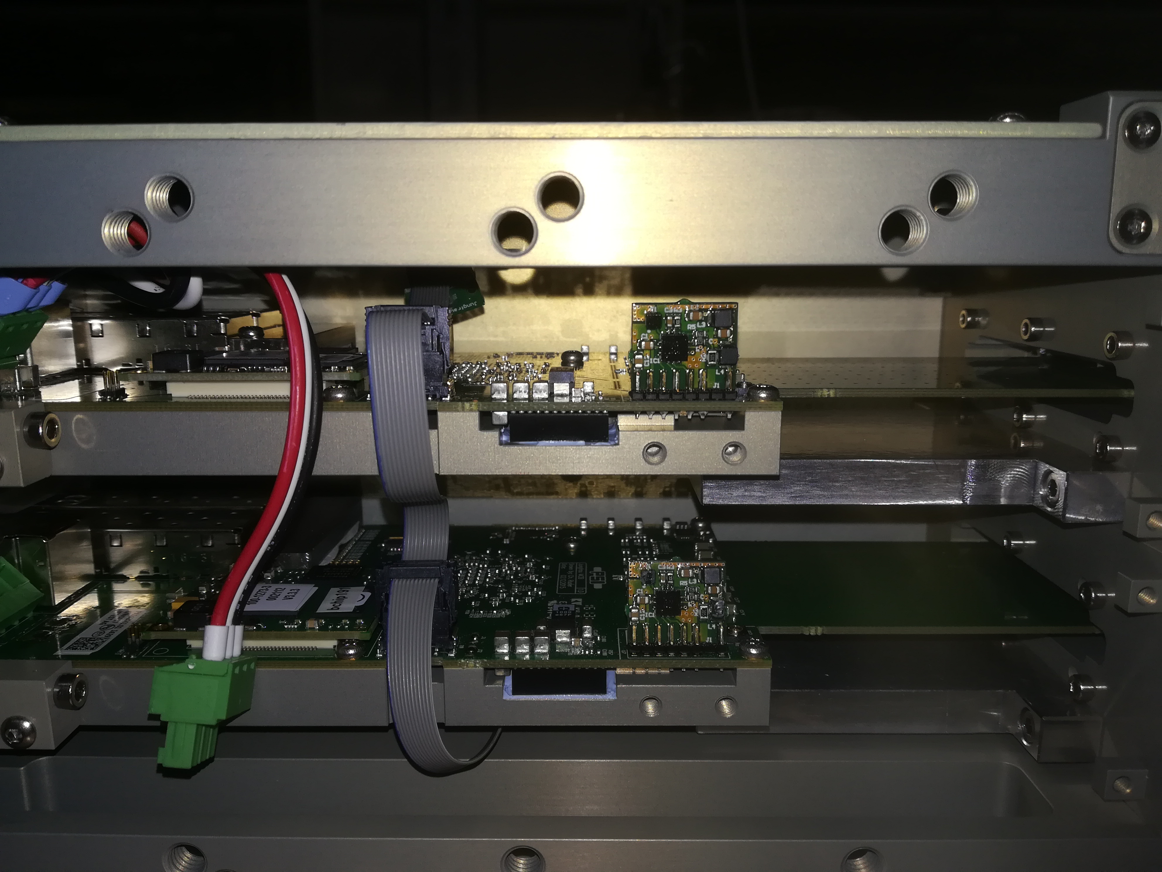
Fig. 12 A detail of a JUNGFRAU board in which the voltage divider is present (the small vertical element of PCB); if this is not present, HV must be externally supplied.
In both cases, HV can range between 90 V and 200 V. There is a slight dependence of charge sharing performances from HV value (the higher the value, the lower the charge sharing), therefore a consistent biasing throughout operation is suggested. For normal operation, a HV value of 180 V is suggested.
To turn off the module, it suffices to turn off the LV. In case the HV is externally applied, it is recommended to switch off the HV first.
Control configuration
The JUNGFRAU CONTROL device communicates with jungfrauDetectorServer running on each module, and therefore controls the module(s) operation, by setting the acquisition parameters, and giving start and eventually stop to the acquisition. Through this device the data acquisition can be started (by clicking on the START button) and stopped (by clicking on the STOP button); the CONTROL START command has of course no impact on the DAQ and its devices, therefore if data needs to be saved, the run has to be started separately from the RUN CONTROL scene.
Basic operation settings: CONTROL device
Important configuration parameters that are present on the CONTROL device are listed below.
Exposure time: expressed in seconds, sets the integration time for the individual memory cell; an exposure time shorter than 2 \(\mu s\) is not recommended.
- Settings: this property sets the feedback capacitor of the CDS:
- gain0: default value;
- highgain0: smaller feedback capacitor for higher amplification in G0 stage;
- Gain Mode: this entry sets the operation mode for the modules:
- dynamic: dynamic gain switching, standard operation mode;
- forceswitchg1: used to measure offsets for G1;
- forceswitchg2: same as above, but for G2;
- fixg1: fixes the feedback capacitance of the pre-amplifier to the one corresponding to G1; no DGS;
- fixg2: same as above, for G2;
the last two settings should be used only in experimental conditions when no gain switching is foreseen, and should not be used to estimate the offset for G1 and G2 in dynamicgain mode, since the presence of the DGS mechanism has some impact on its value.
HighVoltage: if the apposite voltage divider is mounted on the JUNGFRAU Board (shown in Fig. 12), the HV to the sensor can be applied via a command to the jungfrauDetectorServer and this command sets it; a recommended operational value is 180 V, but anything between 90 V and 200 V can be used, depending from experimental requirements.
Delay after trigger: sets the delay for the beginning of the exposure time after the trigger input; expressed in seconds.
Additional Storage Cells: sets the additional number of memory cells to be used during acquisition; it accepts an integer whose value is between 0 (zero, i.e. single-cell operation) and 15 (fifteen, i.e. using all the memory cells).
Storage Cell Start: sets the first memory cell to be filled (the remaining are filled in a round-robin fashion); default value is 15, which is the default storage cell in single cell operation.
Note: Exposure time value and readout rate (whether in autotrigger or external trigger mode) should be compatible quantities; e.g. one should not set 2 ms exposure time, if the device is running in autotrigger with an Exposure period of 0.001 (i.e. 1 kHz).
Basic operation settings: RECEIVER device
The RECEIVER devices have some operational parameters that need to be configured, especially when moving from single cell operation to burst mode operation (i.e. with more than one memory cell per train) or viceversa.
- framesPerTrain: this parameter configures the schema of the data for the DAQ, by setting how many images per train have to be expected; this number has to be equivalent to number of memory cells that are going to be used (e.g. 1 for single cell operation, equal to 5 if only 5 memory cells are used, or 16 if one wants to use the whole memory cell array and so on);
- Storage Cell Start: this parameter needs to have the same value as its equivalent on the CONTROL device.
External trigger and autotrigger
The JUNGFRAU can be operated in two ways: external trigger and autotrigger mode.
To set the detector to operate in external trigger mode, the following parameters of the JUNGFRAU CONTROL must be set:
- Trigger mode: trigger;
- extSig0: communicates the shape of the trigger signal; trigger-in-rising-edge is the viable option for EuXFEL trigger;
- Number of Triggers: this sets how many trigger inputs the detector must accept before declaring the measurement terminated; in normal operation, this is set to the desired number of trains to acquire;
- Number of frames: this sets the number of acquisitions per trigger; it is normally set to 1 in external trigger mode;
- Exposure period: this dictates the acquisition period at the end of which the ASIC is read out; it is irrelevant if Number of frames = 1;
Conversely, to operate the module in autotrigger mode, the CONTROL device must be set:
- Trigger mode: auto;
- Number of Triggers: 1;
- Number of frames: set to the desired number of acquisitions;
- Exposure period: this regulate the period between frames at the end of which the ASICs are read out and it must be expressed in seconds; we suggest not to exceed ~100 readouts per second, otherwise there may be packet loss.
To have an estimate of the total output, the following formula can be used:
In single cell operation \(N_{memcells} = 1\) (obviously); in burst mode operation the number of memory cells used is configurable and ranges from 1 to 16.
Note: it is strongly suggested to terminate an acquisition properly, i.e. by pressing STOP or waiting that the set number of images is acquired. Improper termination of an acquisition will likely lead the devices in ERROR state.
Single cell and ‘Burst’ operation modes
The detector can be configured to acquire one image per acquisition cycle (i.e. before reading out the image), or to use more than one of the sixteen storage cells: these two operation modes are referred to as single-cell and burst operation mode, respectively. Since the readout time of one single image is of about 819 \(\mathrm{\mu}s\), burst mode is necessary to acquire more than one image per EuXFEL train.
To properly configure the detector, some properties have to be changed both in the CONTROL and RECEIVER devices.
| Device | Property | Single | Burst |
|---|---|---|---|
| CONTROL | Additional Storage Cells | 0 | 15 |
| RECEIVER | Frames per Train | 1 | 16 |
| RECEIVER | Burst Mode | False | True |
It is recommended NOT to change the property Storage Cell Start and instead leave it to the default value of 15. NOTE: it is important that the DAQ is set in IGNORE while the detectors are being reconfigured, since the schema is updated every time the Apply Configuration is called, and it is done via reading the receiver Frames per Train property: forgetting to do so will eventually result in data being saved in arrays of the wrong shape.
It is also important to note that, for details linked to the firmware, the delay between the trigger signal and the first exposure gate opening slightly increases when switching to burst operation mode, and it recommended to always control the synchronization between pulses and gates on the oscilloscope.
In burst mode the CONTROL device property Exposure Timeout can be used to further increase the dead time in between acquisition gates with respect to the factory minimum of 2.1 \(\mathrm{\mu}s\). Default value for this property is 25 ns (cannot be reduced): any value larger than that can be entered (in nanoseconds) when the CONTROL device is unistantiated.
Temperature Control
There is the possibility to set a Temperature Control based on the temperature readout of the sensor on the Jungfrau board: if a certain temperature threshold is passed, the firmware will power off the ASICs of the FEM. The possibility to set up this safety check is implemented in the Karabo CONTROL device through five properties:
- Temperature threshold: is the threshold that needs to be passed to trigger the Temperature Event; default is 65 \(^{\circ}C\), but it can be set at will and a different threshold can be set, if needed, for each module controlled by the same CONTROL device; if only one entry is left, it will be applied to each module;
- Temperature Control: when set to ‘1’ (default is ‘0’) enables the temperature control;
- Temperature Events (Modules): a list of results of the temperature control, for each module; when it changes to ‘1’, it means that that particular module triggered a Temperature Event (i.e. it passed the set threshold);
- Temperature Event (Summary): a single boolean summarizing the status of the whole detector, by doing the OR of all Temperature Event output of each module;
- Reset Temperature Event: a button that resets all the Temperature Events to 0 (zero); of course, if the problem that caused the event persists, it will be triggered again, so it is recommended to click the Reset button only after investigation.
Of course, the status of the Karabo device properties will be refreshed on a rate depending from the Polling Interval property (default is 20 s).
Once the control is activated, the temperature checks are performed on the firmware level. This is done because (almost) all the software communications between detector and client are done, for each module, on an individual TCP port, which also means that during acquisition this port is constantly busy (so no real time updates are possible): therefore the Karabo device status will not update during acquisition, but the Temperature Control will work nonetheless. If the event has been triggered during an acquisition, it will become apparent on the RAW image preview, which will show just the ADC baseline output (similar to what is shown in figure Fig. 20). Stopping the acquisition will then lead the Karabo CONTROL device to update its status, and the condition of the Temperature Control will become apparent.