Troubleshooting
How to use Command Line Interface
The Karabo devices working with detectors developed at Paul Scherrer Institut make use of the control software developed there, called SLS Detector Software [1]. This software packages allowes to operate the detectors from Command Line Interface (CLI). For all the detectors installed at EuXFEL, it is always possible to use the CLI in parallel to the Karabo devices or in their place if the CONTROL device has issues. in order to do so, however, xctrl access to the Host running the CONTROL device is needed.
In order to run multiple CONTROL device instances on the same Host, every time a CONTROL device is instantiated, it reserves a different segment of the shared memory, and identifies it with a randomly generated DETECTOR_ID; to use the CLI in parallel to Karabo it is therefore necessary to know the last DETECTOR_ID generated. To do so one should look in the /dev/shm folder in the Host:
ssh as xctrl to the Host and run:
source karabo/activatego into the /dev/shm folder and run:
ls -lrthYou should see a list of entries like the ones in figure :numref:’label_dev_shm’. We are interested in the last entries of this list and in the multiple digit number before the word ‘_module’: this is the DETECTOR_ID that is needed (‘657808900’ in the example). The second integer number is the MODULE_ID, in case of multi-module detectors.
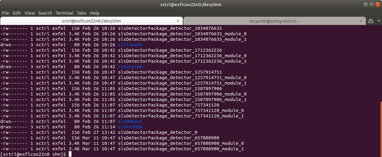
Fig. 17 Screenshot of the list of entries in the /dev/shm folder in a Host running slsDetector instances
At this point, the syntax to send a command is
sls_detector_put DETECTOR_ID-MODULE_ID: <command>
For example, if we want to stop the acquisition of the detector in figure Fig. 17 we will run:
sls_detector_put 657808900-0: stop
and for the slave:
sls_detector_put 657808900-1: stop
Similarly, to retrieve a parameter value:
sls_detector_get DETECTOR_ID-MODULE_ID: <parameter>
Continuing the above example, if we want to retrieve the number of frames set:
sls_detector_get 657808900-0: frames
Note: the CONTROL device clears the shared memory when it is shut down, so the above mentioned procedure is necessary only to work in parallel to the CONTROL (maybe to set commands not exposed in Karabo) or when the CONTROL device is in ERROR or not responsive, but before shutting it down.
How to update firmware and server
In order to upgrade the firmware version the CLI needs to be used. The slsDetectorSoftware client version has to be the same version as the one of the server running on the detector in need of an upgrade.
For server versions above v6.1.1 and for detector running a version of firmware and software mutually compatible, a description is given on PSI FW_Upgrade page. The description assumes however expert users.
A more detailed description is given here:
Once the client has been initialized, clean the shared memory with:
sls_detector_get freeSet up the network:
sls_detector_put hostname MODULE-HOSTNAMECheck the “Hardware version” (i.e. if the module is using a Jungfrau MCB v1.0 or v2.0) with:
sls_detector_get versionsThis command should return a list of all the software and hardware parameters of the module under consideration. Check the “Hardware version” item of the list. It should either be “1.0” or “2.0”. This is relevant, because different versions of the board need different versions of the firmware. Select the FW version according to the compatibility table on the SW_Releases page of PSI.
In order to update both server version and firmware, run:
sls_detector_put update jungfrauDetectorServervxxx xxx.pofOtherwise, to just update the firmware, run:
sls_detector_put programfpga xxx.pof
where jungfrauDetectorServervxxx and xxx.pof indicated respectively the server file and the .pof file containing the firmware upgrade instructions, which should be located in the directory where the command is being launched. The procedure will last a few minutes, and progress will be communicated on the command line output.
Older client versions or incompatible SW and FW versions
- In this case, a lot of the steps hidden in the
updatecommand must be done explicitly. The following instructions - assume that the module has automatic server restart.
Copy the new the jungfrauDetectorServervxxx to the module:
In the directory where the server is located, run:
python3 -m http.servertelnet on the JUNGFRAU module Blackfin:
telnet MODULE-HOSTNAMEFrom the module command line, copy the server:
wget http://HTTP-SERVER-HOST-NAME:8000/jungfrauDetectorServervxxx
From the Blackfin command line, set up the new server to run in update mode:
Give the server run privileges:
chmod 775 jungfrauDetectorServervxxxCreate a symbolic link:
ln -sf jungfrauDetectorServervxxx jungfrauDetectorServerRemove the automatic respawn of the server. Open the inittab file with, e.g.
vi /etc/inittabAfterwards, comment out the line
ttyS0::respawn:/jungfrauDetectorServerReboot the Blackfin chip by running the
rebootcommand. This should kick you out of the module.
After reboot, telnet again on the detector Blackfin and start the server in update mode:
./jungfrauDetectorServer --updateFrom the client PC, clean the shared memory:
sls_detector_get freeSet up the network:
sls_detector_put hostname MODULE-HOSTNAMEUpdate the firmware:
sls_detector_put programfpga xxx.pofTelnet again on the Blackfin and remove the comment on the
/etc/inittabfile that prevented automatic respawn; Afterwardsrebootagain the Blackfin.After restart, remove the update mode:
sls_detector_put updatemode 0
Emergency shutdown
First of all, do not panic. Generally speaking, it is very difficult to permanently damage a JUNGFRAU module; examples of these kind of extreme cases may be:
- mechanical damage to the sensor (scratching the sensor, touching the wire bonds, etc.);
- elevate doses delivered to the sensor and/or the electronics (e.g. direct unattenuated XFEL beam);
- apply a voltage value outside specifications (e.g. low voltage higher than +12 V, or with inverted polarity);
- apply high voltage with air pressure around Paschen’s Law minimum (for air, it around 0.01 mbar);
- prolonged operation without cooling in place can also be damaging.
In case of an emergency, when it can be necessary to put the detector in a safe state (e.g. a vacuum leak), one can simply di the following:
- power down the detector, by powering off the LV; since the HV is generally delivered to the sensor via a voltage divider mounted on the JUNGFRAU board, this will also bring the HV down; if possible use your standard power off procedure, otherwise, exceptionally, it is also possible to power it off by simply removing the power plug from the power supply: it is in fact not recommended to do it by removing the green connector that is plugged directly into the JUNGFRAU board (see Fig. 4); if necessary, disconnect the power supply to prevent an uncontrolled power up without cooling;
- turn off the cooling;
- mount back the cover plates to protect the sensor.
When the emergency is recovered and the situation is back to normal operation, it should be possible to bring the module back to operation following the normal power up procedure.
Following, the most common problems encountered so far with the JUNGFRAU operation will be listed, and possible solutions presented. Anyhow, a few sanity checks should be performed as preliminary, to rule out simple mistakes:
- check power;
- check connectors, in particular the network (i.e. fiber and RJ45);
- check that the module is responding:
- ping it as described in Control and operation;
- if necessary telnet on it to check that jungfrauDetectorServer is up and running.
Raw preview
No image on the preview and the RECEIVERS are not updating
If the Frame Rate In field of the RECEIVER is stuck to zero, it is probably a problem of network configuration.
Check that the module is up and running (ping it); if not sure, reboot it as explained below in Control and operation;
check that the fiber is connected and that there’s signal (LEDs below the interface are both shining blue);
check that the IP addresses are correctly configured;
if all the above points are satisfied, probably ITDM or Controls on OCD must be called; possible further misconfigurations are:
- the RECEIVER interfaces on the host PC must be configured so that MTU = 9000;
- the UDP Socket buffer size must be = 2000 * 1024 * 1024 = 2097152000;
- if both conditions are met, this is a problem for experts
I can see the RECEIVERS updating but no image on the preview
If the frame rate of the receiver updates, it should be receiving data; if no image is seen on the preview, try opening the corresponding RECEIVER device and setting ‘Online display enable’ as ‘True’ (see Fig. 18)
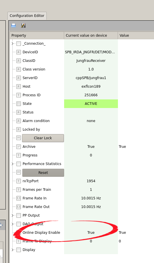
Fig. 18 The setting to be marked as ‘true’ to allow online display
There are striped artifacts in the image
It has been reported the presence of striped artifacts in the online preview. The shape of the stripe indicates different problems.
The stripes are horizontal, i.e. they manifest on the raw image as bands of uniform value equal to zero across all the columns (see Fig. 19); this effect indicates packet loss: some of the UDP packets sent out by the JUNGFRAU module(s) are not collected by the RECEIVER device; this is probably due to some misconfiguration of the network and Controls should be called.
The stripes are vertical, i.e. they manifest themselves along the columns, may or may not stop at half module, and they are overlaid on the signal. First, stop the acquisition and check if your module triggered a Temperature Event (see Temperature Control for details). If this is not the case, check the raw data of your dark
runs; if the artifacts are in there as well and their structure looks similar to what shown in
Fig. 20, the problem is with the FPGA in the JUNGFRAU board. Power cycling the module has been reported as a solution to this issue.
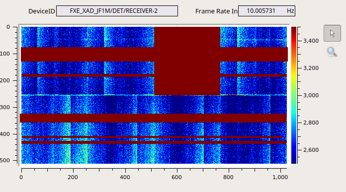
Fig. 19 Example of raw output indicating incomplete frames, i.e. with UDP packet loss
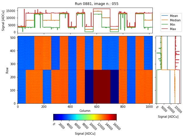
Fig. 20 Raw output when the FPGA on the JUNGFRAU board is not behaving correctly
Large parts of the detector have a baseline too high
The RAW image output of the detector display large non-uniformities, in which the baseline of the detector is too high of several hundreds if not thousands ADC units, which look like large spots on the detector surface, similar to what is shown in Fig. 21. In this case, it is very likely that the detector is not properly cooled, and the non-uniformities are simply the effect of the sensor generating higher leakege current due to inefficient heat dissipation: power down the detector and check the cooling; if it off or not working properly (e.g. set to a temperature too elevated) bring it back to normal, let it run for a few minutes and then power back the detector.
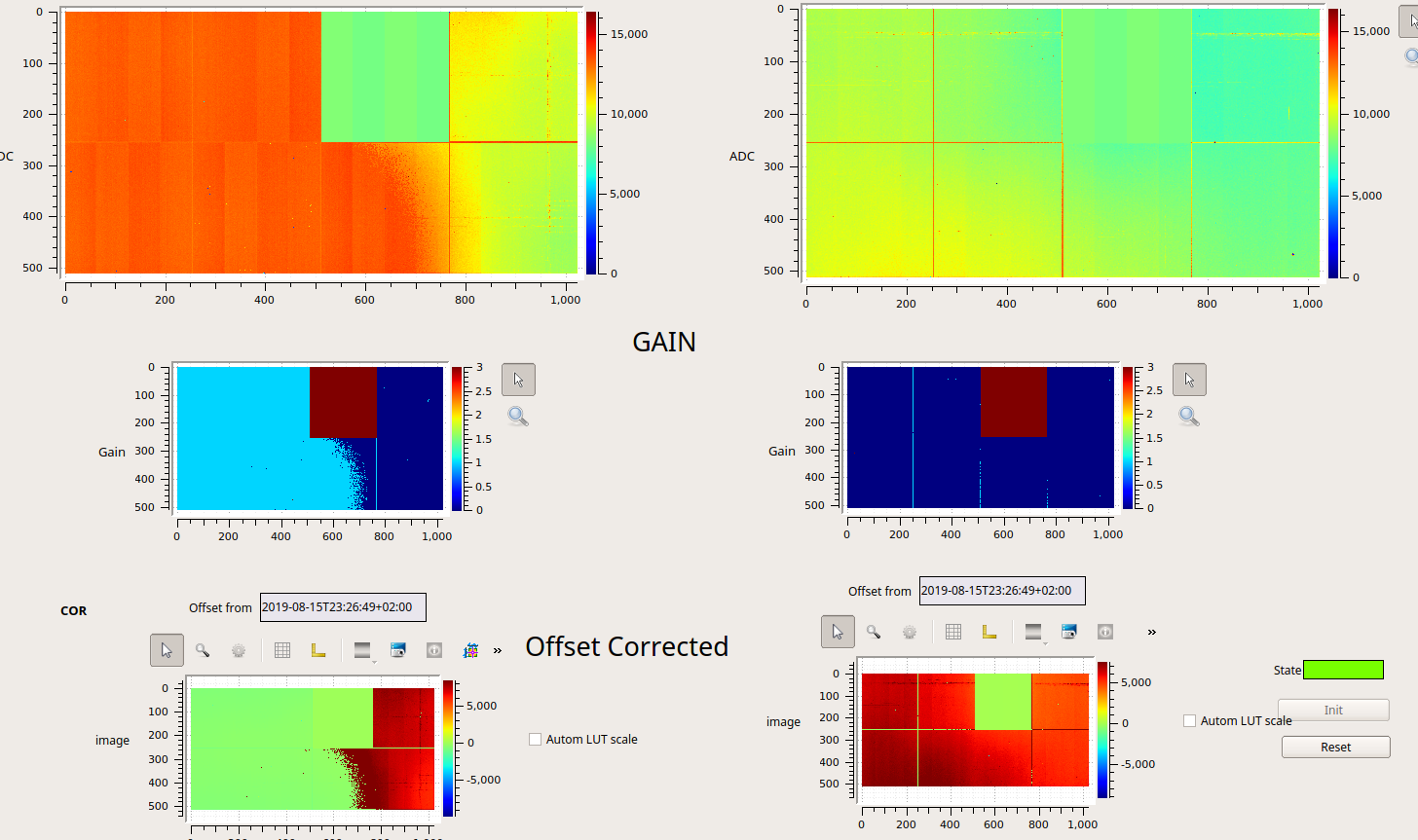
Fig. 21 Example of overheated JUNGFRAU modules: probably due to a combination of long exposure time and cooling failure, the leakage current alone is enough to bring some pixels to G1.
Control and operation
My CONTROL or RECEIVER device is in ERROR
There is an order in which these devices must be instantiated. To recover, try:
- shut down all the devices (or even the server device, for good measure);
- instantiate all the RECEIVER devices first;
- once the RECEIVERS are up, instantiate the CONTROL device.

Fig. 22 The device servers for the operation of three modules at SPB: after shutting them down, the three RECEIVER devices (here named ‘MODULE’) must be re-instantiated, before instantiating the CONTROL device
I have instantiated the devices in the correct order, but devices ar still in ERROR
At this point, it is probably necessary to restart the jungfrauDetectorServer running on each module. Shut down all the JUNGFRAU devices and proceed with the restart of the jungfrauDetectorServers.
Suggested method:
a list of the microcontroller aliases can be found in the detectorHostName list in the CONTROL device (see Fig. 23); connect via telnet the microcontroller on each JUNGFRAU module using that aliases, e.g.: from command line type:
telnet spb-irda-jngfr-det-control-1(see Fig. 24);
once on the module, from the command line, launch the reboot command (see Fig. 25); this will reboot the embedded LINUX OS on the microcontroller and the jungfrauDetectorServer will automatically respawn;
repeat this for each module.
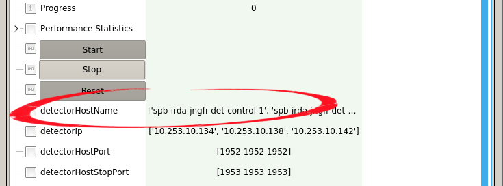
Fig. 23 The list detectorHostname contains the aliases of the microcontrollers on each JUNGFRAU board
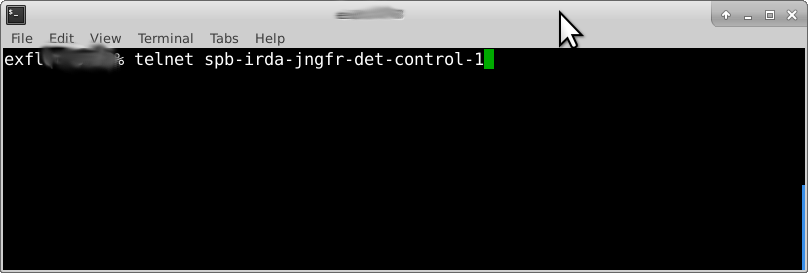
Fig. 24 Example of telnet use to connect to a microcontroller
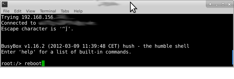
Fig. 25 After connection to the microcontroller, launch the reboot
Not suggested method:
it is possible to obtain the same result by simply power cycling the modules; however, frequent power cycles are obviously not recommended. It is strongly suggested to use this option only if the individual reboot is not possible.
After the reboot of the jungfrauDetectorServers (you can ping the module microcontrollers to check if they are up again, see Fig. 26), re-instantiate the devices in the correct order.
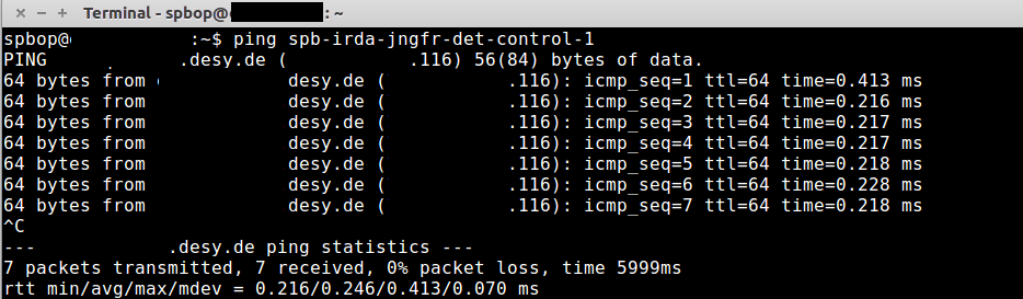
Fig. 26 Ping the module to see if the reboot has been completed
Despite reboot of the modules and correct instantiation of the devices, they are still in ERROR
If this is the case, it may be necessary a reboot of the physical host where the server devices are running; if you have the permits to do so (i.e. to ssh to that machine and start a reboot), and feel confident in doing it, go ahead and do it; after it is done, reboot the controllers on the JUNGFRAU modules as explained above and then re-instantiate the JUNGFRAU devices in the correct order. Otherwise, Controls OCD needs to be called.
External trigger acquisition does not work
This is under the assumption that it has been verified that acquisition in autotrigger mode is instead working.
Check if LED near the LEMO connector (see Fig. 4) is flashing:
if it’s not flashing:
- check with a scope that input signal is actually a valid trigger: TTL, positive, at least 100 ns;
- access the module and check that the flat cable is correctly connected both to the trigger board and the JUNGFRAU board;
- if both conditions are satisfied, try to replace the trigger board or leave it to the experts;
if the LED is flashing and still acquisition does not work, try a reboot and restart as explained in My CONTROL or RECEIVER device is in ERROR; if this does not work either, it is a problem for experts.
Footnotes
| [1] | https://slsdetectorgroup.github.io/devdoc/ |