Network setup
This section will illustrate the generalities on how to configure the network between the control machine, the JUNGFRAU module(s) and the receiver server.
Basic components
The control and operation of JUNGFRAU modules is performed through the use of a software package developed at Paul Scherrer Institut, called SLS Detector Software [1].

Fig. 7 Schema of the architecture of the SLS Detector Software Client-Server-Receiver network. The picture is taken from the “Quick guide to the SLS Detectors Package” by PSI Detector Group
The basic architecture of this software is common to all the detectors developed at PSI and is depicted in Fig. 7 for a GOTTHARD module; to summarize, it consists of three elements:
- a client, running the SLS Detector Software, from which commands are launched;
- a server running on the detector module, which receives the commands from the clients and consequently controls the ASICs (jungfrauDetectorServer);
- a receiver, which collects the data sent out of the module in form of UDP packets.
This software is then wrapped in Karabo, and can be used via the standard Karabo GUI interface:
- a CONTROL device will allow to launch SLS Detector Software commands;
- a RECEIVER device will collect the data packets.
In principle, the client and the receiver can be running on two separate machines, but in practice, at EuXFEL, the corresponding devices will be running on the same server.
Device configuration
In order for the network to function properly, there are three ports that need to be configured as part of the same subnet of the client:
- a 100 Mb port for control on the JUNGFRAU module, where the commands issued by the client will be sent, to be received by the jungfrauDetectorServer;
- a 10 Gb port for the data output on the JUNGFRAU module (indicated as 1 Gb on the picture);
- the port on the receiving server, to which the jungfrauDetectorServer will send the UDP packets to be collected by the RECEIVER device.
To configure these parameters, one must access the CONTROL device before instantiation.
- Detector Hostname configures the control port on the JUNGFRAU module; at EuXFEL this is usually accomplished by inserting here the alias corresponding to the microcontroller mounted on the JUNGFRAU board; this alias is usually assigned by ITDM at the moment of registration of the module MAC address;
- RX UDP/IP configure the IP address of the port on the physical server to which the RECEIVER device must listen to; usually this IP addess is assigned by ITDM;
- Detector UDP/IP configures the IP address of the data out port on the JUNGFRAU module; it can be any address, but it must be chosen so that it is in the same network of the other two.
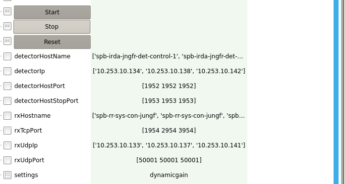
Note: all these fields in the CONTROL device are actually lists; to control more modules simultaneously, it suffices to insert all the parameters for every module in each list; one must pay attention that the parameters for a particular module are inserted always at the same position in each list (see e.g. Fig. 8).
Additionally, TCP ports on the RECEIVER and UDP ports on the CONTROL need to be configured.
The RECEIVER device has the default TCP port of 1954 and this value can be safely used when just one module is used; when more modules are in use, each RECEIVER must be configured to a different TCP port:
- go to each RECEIVER device before instantiation and set RX TCP Port field to the desired value (e.g. 1954 for the first RECEIVER, 2954 for the second and so on, see Fig. 9);
- go the CONTROL device and fill in the RX TCP Port list with the values assigned to each RECEIVER (see e.g. Fig. 8).
Configure the UDP port value is useful only if there are more than one RECEIVER device listening to the same IP address; if this is not the case (and it normally isn’t at EuXFEL), the default value for RX UDP/IP Port of 50001 can be used.
Finally, the name of the server which hosts the RECEIVER must be configured:
- on the uninstantiated CONTROL device, set RX Hostname to the name of the server machine where the RECEIVER device is running, e.g. exflconXXX.
Software and firmware compatibility
The detector group at PSI routinely releases new versions of the SLS Detector Software. Before updating the client installation, one has to make sure that the new version is compatible with the firmware installed on the boards. In case of doubt, please consult the PSI Software Releases page.
In order to check the version of the firmware, there are two possibilities:
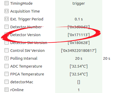
- from command line: from a shell of the machine where the client is running (after configuration, see Device configuration), type: sls_detector_get detectorversion; you should get a number formatted as hexadecimal like: 0x171113; this number is the date of release of the firmware, which identifies it (in the example corresponds to 13.11.2017);
- from the CONTROL device: there is a field in the CONTROL deice that checks the firmware version (see Fig. 10); there it can be seen the release date of the firmware, formatted as hexadecimal.
| [1] | https://slsdetectorgroup.github.io/devdoc/ |


