Feedback Algorithm
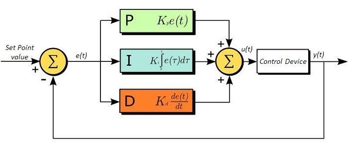
Since the feedback mechanism has to be robust to wrong configuration, it is based on the PID (proportional–integral–derivative) controller, which is a control loop feedback mechanism widely used in industrial control systems requiring continuously modulated control 3. A PID controller continuously calculates the deviation of a measured value \(x\) with respect to the reference value (set-point SP); this deviation is typically referred to as “error value” \(e\):
The controller attempts to minimize the deviation over time by adjustment of a control variable \(u(t)\), such as (in our case) the orientation of a steering mirror, Fig. 7. This correction is based on proportional, integral, and derivative terms of the deviation (whose constants are denoted as \(K_P, K_I\), and \(K_D\) respectively):
with
and \(K_{calib}\) being a conversion calibration constant converting the determined \(PID\) value to the actuator units (e.g. mV when dealing with piezo motors steering a mirror). In order to deliver a constant set a PID parameters a conversion factory between error value and actuator hook is implemented
The feedback action for the actuator position \(z\) is then build via the following steps:
Previous actuator value: \(z_{old}\)
Proposed actuator value: \(z_{new}\) = \(z_{old} + u(t)\)
In real data acquisition we are dealing with discrete accumulation (sum) of measurements. The position values are stored in a FIFO buffer of size ten. When the buffer is filled a new position for the actuator is calculated, and as soon as a new event is received, the first measurement which entered the buffer is removed, to allow the most recent measurement to be stored in the buffer. The integral term takes into account only the current elements in the filled buffer (i.e., the last ten provided measurements) and does a smooth (running) average to prevent an overshooting (windup) of the actuator. The derivative term is calculated as the difference of last two measurements over the difference between their timestamps.
Those three parameters \(K_P, K_I\) and \(K_D\) give the response of the control variable with respect to the deviation, the integrated (sum) deviation, and the derivative (rate of change) of deviation, respectively. Note that in the XrayFeed device these parameters are labeled as “Const. P.”, “Const. I.” and “Const. D.”, respectively. Tuning a PID controller is the process of determining the ideal values for P, I, and D to achieve the desired response; e.g., in some systems, one may want the control variable to reach the set-point as quickly as possible limiting overshooting actions (thus without moving further the set-point). The default (hard-coded) parameters, allowed for finer-tuning in administration access mode, are:
\(K_P\): |
3.0 |
\(K_I\): |
0.1 |
\(K_D\): |
0.5 |
The conversion factor \(K_{calib}\), as well as the PID parameters, is provided by the group responsible of the feedback devices, and is obtained by calibration. Using the above values for the PID parameters, and depending on the specific choice of devices, the following calibrated values (hard-coded in the software) are used:
Detector |
Actuator |
\(K_{calib}\) |
|---|---|---|
SPB_XTD9_XGM/XGM/DOOCS |
SA1_XTD2_MIRR-2/ACTRL/RY |
0.000100 |
FXE_OGT1_CAM/SPROC/CAMERA |
SA1_XTD9_MIRR/ACTRL/RY |
0.000249 |
FXE_OGT1_IPM/MDL/MONITOR |
SA1_XTD9_MIRR/ACTRL/RY |
0.000100 |
- 3
John Bechhoefer, Feedback for physicists: A tutorial essay on control, Rev. Mod. Phys. 77, 783
