Device Initialization
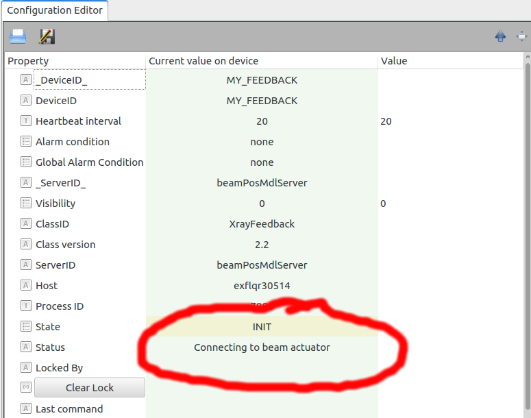
At initialization stage the feedback device connects to the selected devices and shows some of their parameters relevant to the feedback. In case a choice of incompatible devices is done, e.g. selecting a monitoring device for SPB and an actuator of FXE, the program will raise an error. In case one device is unreachable, e.g. because not instantiated yet, the program will remain in the state INIT and its status will report it, e.g., reporting “Connecting to beam actuator” in case of failing connection to the actuator, Fig. 3.

Fig. 3 Fig. 3: The device remains in the INIT state when trying to connect to an actuator which is not reachable.
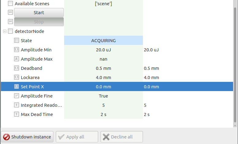
Once the device is correctly initialized, relevant parameters of the monitoring device are accessible as a “node” in the configuration editor, Fig. 4, and are described in the following:
State: The state of the detector device;
Amplitude Min: The minimum signal seen by the detector to validate beam;
Amplitude Max: The maximum signal seen by the detector to validate beam;
DeadBand: The range of values for the beam position considered as accepted by the feedback control; no action will be taken by the device in this scenario;
Lockarea: The range of values for the beam position which are rejected by the feedback control; the device will propose thus an action to be taken (a new value for the actuator) in order to bring the beam position within the allowed deadband. Note that in case of values outside the lockarea, although not good for the beam, the device will take no action to correct the beam position, and the FIFO buffer will be emptied.
Set Point X: The reference point of x coordinate of the beam position on the detector used for feedback control;
Amplitude Fine: A Boolean flag notifying whether the signal amplitude is within the allowed region;
Integrated Readouts: Number of readouts to consider in the running average;
Max Dead Time: Maximum accepted time interval between two consecutive readouts.
Some of these properties can be tuned by the user at run-time; as for every karabo device this can verified by clicking on the parameter “Value” field in the configuration editor. For some monitoring device (as for XGM) there is no need to set an upper threshold for the signal. The default values set to the properties are typically agreed with the corresponding detector experts.
The following three important booleans are accessible to the user to monitor the status of the device environment:
Valid Measure: Should be “True” in case the current signal amplitude is within the allowed region, and the FIFO buffer for evaluating a running average is full. Note that the signal is also considered not fine in case the interval between two consecutive measurements is larger than the allowed dead-time;
isWaiting: Should be “True” in case the current signal amplitude is within the allowed region, and the FIFO buffer for evaluating a running average is not yet full. This property is typically True soon after the initialization stage or after a wrong amplitude was found;
Valid Environment: Should be “True” in case the safety check of the device environment was successful (to be implemented).
The FIFO (first-in first-out) buffer is described later in this documentation.

Fig. 4 Fig. 4: At initialization a node is created in the configuration editor to show relevant properties of the monitoring device.
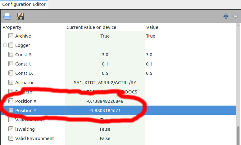
The position of the x-ray beam (“Position X” and “Position Y”) on the selected monitor is shown in the editor relatively to the reference value, and is updates at the rate provided by the connected device, Fig. 5. The reference one, initially is set to null (virtually at the center of the monitoring device), can be changed at run-time by the user. The update will proceed also when the XrayFeed has not started its feedback activity yet.
