4. Powering ON the DSSC detector and sending data to DAQ
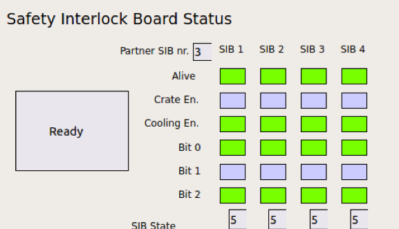
The DSSC detector can be powered ON if in vacuum and cold. The temperature of the cooling blocks of the DSSC detector can be seen in the SIB scene. In the same scene, at the top, a set of indicators turn from blue to green. The DSSC detector can be switched ON only if all the four Crate En. indicators are green and the status is Operation. In Fig. 4.1, a detail of the SIB scene is shown, where the SIB signals are visible. In the figure, the status is ‘Ready’ (SIB state 5), meaning that the DSSC detector is ready to be cooled down (vacuum level is OK). When the temperature of the cooling blocks goes below -10 degC, the Crate En. signal becomes also high and the status goes to Operation (SIB state 6). In this configuration the detector is ready to be powered up.
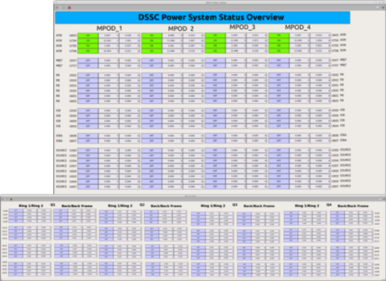
The DSSC detector is powered by four MPOD power supplies (one for each of the quadrants) each having low voltage and high voltage channels. Different scenes are available to monitor the powering status of the detector, they are shown in the pictures. Fig. 4.2 shows the status of the low voltage system of DSSC once powered on. The status of the four power supplies (MPOD_1 to MPOD_4) is shown. The channels are grouped corresponding to the ordering of the powering on procedure (channels turn ON from top to bottom at different stages). The names of the channels refer to the different tags used also in the power procedure. In the picture, all the quadrants low voltages are ON and the ASIC are correctly programmed.
Fig. 4.3 shows the status of the high voltage system of DSSC once powered on. The status of the four power supplies (MPOD_1 to MPOD_4) is shown, two columns per MPOD are needed.
The MPOD power supplies feature a web interface which updates faster than the Karabo GUI and it also allows seeing the channel settings. It can be opened by typing the MPOD IP in a browser window (on the control network). The IP addresses of the MPODs are the following:
| Quadrant | SCS DSSC MPODs | SQS DSSC MPODs |
|---|---|---|
| Q1 | 192.168.177.91 | 192.168.158.133 |
| Q2 | 192.168.177.92 | 192.168.158.134 |
| Q3 | 192.168.177.93 | 192.168.158.135 |
| Q4 | 192.168.177.94 | 192.168.158.136 |
4.1. DSSC setup for data taking
The procedure to switch ON the detector proceeds in three general steps which are explained in detail later on in this chapter. These steps are:
- Switching ON the in-vacuum electronics up to the ASICs (see Section 4.2).
- Configuring the detector electronics and verifying this by sending data to the XFEL DAQ (see Section 4.3).
- Switching ON the rest of the in-vacuum channels (source voltages and sensor voltages, the latter are high voltage channels). (see Section 4.4).
All that is required to set up the DSSC detector for data taking is available in the DSSC_Main scene:
SCS(SQS)_DSSC \(\rightarrow\) DSSC_Main
The powering of the detector is handled by the Automatic Power Panel in the DSSC_Main scene, the configuration by the PPT/ASICS Configuration Panel in the same scene.
4.2. Switching ON the in-vacuum electronics up to ASICs
Open power system monitgorng scenes from the DSSC_Main scene, go to Automatic Power Procedure panel and click on LV Channels Staus and then HV Chanels Status links, that will open LV and HV voltages monitoring scenes.
OR
In navigate to the DSSC powering Karabo subproject: SCS(SQS)_DSSC \(\rightarrow\) Subprojects \(\rightarrow\) DSSC_POWER and open the scenes:
DSSC_Power_Status(monitoring low voltages and currents)DSSC_hv_status(monitoring high voltages and currents)
The quadrants are switched on using the Automatic Power Panel in the DSSC_Main scene. It must be first checked that the channels AON in the DSSC_Power_Status scene are all ON (see Fig. 4.4).
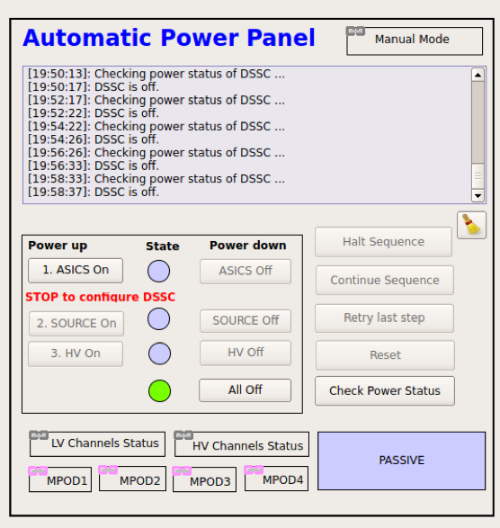
The detector needs to be first powered up to the ASICs. To do that, press the ASICS ON button in the auto_power scene (Fig. 4.5). Wait until all the channels in the DSSC_Power_Status up to IOBA become green. SOURCE channels shall still be blue (OFF).
When all the channels up to IOBA are green, the detector is powered up to the ASICs and the ASICs need to be programmed at this stage.
4.3. Configuring the detector ASICs
In this state, having a look at the log file of the PPT FPGA can be very useful. However, this requires access to the DSSC control server, exflcon145 for SCS and exflcon202 for SQS, which are NOT accessible to everybody with an XFEL account. If you do not know if you have access to that server, you probably do not.
- To open the interesting log file, the procedure is the following:
- Log in to
exflcon145orexflcon202asxctrl. source karabo/activatekarabo-xterm cppserver_scs_dssc_det
- Log in to
An xterm will appear which will log the changes in the FPGA.
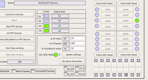
To go on programming the ASICs, with only the ASICs ON, move to the PPT/ASICS Configuration Panel in the DSSC_Main panel (see Fig. 4.6).
For each quadrant, the proper configuration files have to be loaded. The configuration files are different for each quadrant, while the settings for gain are the same. A list of config files is available in a drop-down menu under each SCS_CDIDET_DSSC(SQS_NQS_DSSC)/FPGSA/FPGA_Qi device.
To load the config files, the devices must be in shutdown state. Make sure that the proper configurations are uploaded for all quadrants! Check the config file name in the FPGA_Qi device under ‘Full Config File’. Check that the ‘Quadrant ID’ is correct for all the quadrants.
When the config files are loaded, instantiate the FPGA_Qi devices by right clicking on the cppServers/scs_dssc_det (which you can see also above) and selecting ‘Instantiate all devices’. Wait until they all become green.
Then press Start PPT devices in the PPT/ASICS Configuration Panel.
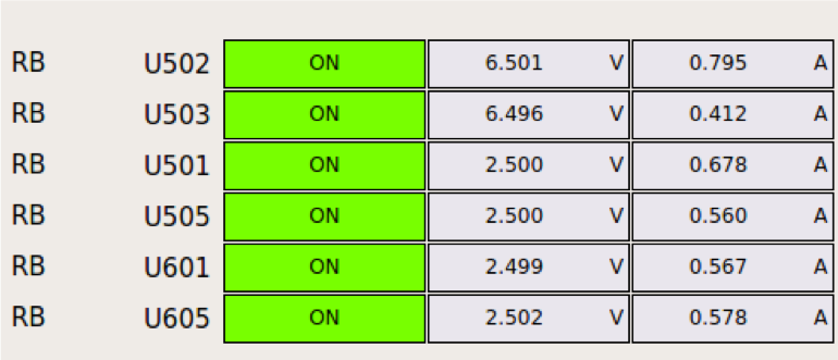
In this phase, the currents of the IOB channels (500, 504, 600, 604) shall go from ~300 mA to 850 mA. This means that the IOB are being programmed. This step can take several minutes, as the IOBs are programmed one after the other. Monitor the currents in the DSSC power system status scene. The currents of the RB channels (501, 505, 601, 605) will go to zero. If the IOB channels do not go to 850 mA, something has gone wrong. Press the ‘Start PPT devices’ button again.
When the ‘Start PPT devices button becomes active again and the IOB currents are fine, press Init PPT devices in the PPT/ASICS Configuration Panel.
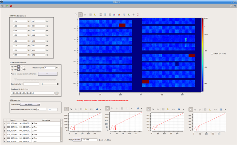
The currents of the RB channels will go between 400 and 600 mA. The system is programmed when the ‘Init PPT devices’ button becomes active again. If any of the RB channels do not show current, repeat the procedure. Press Start Data Sending in the PPT/ASICS Configuration Panel, and DSSC will start sending data. To monitor the data sent, open the PREVIEW scene in the DSSC_ONLINE_CAL project. In order for the scene to show the DSSC data, the DAQ shall be configured properly (see Section 5). The currents of channels 500, 504, 600 and 604 should go up to to ~900 mA. If the currents show these values, the system is properly programmed. If this is not the case, repeat once again ‘Init PPT devices’ and then ‘Start Data Sending’.
At this point, many ASICs can still be flickering, namely, they will rapidly change color and pattern in the PREVIEW. This means that they are not sending data properly. To repair this, press the button ‘ASICs/Reset on PPT’ in the DSSC_CONTROL scene. You might need to repeat this step more than once.
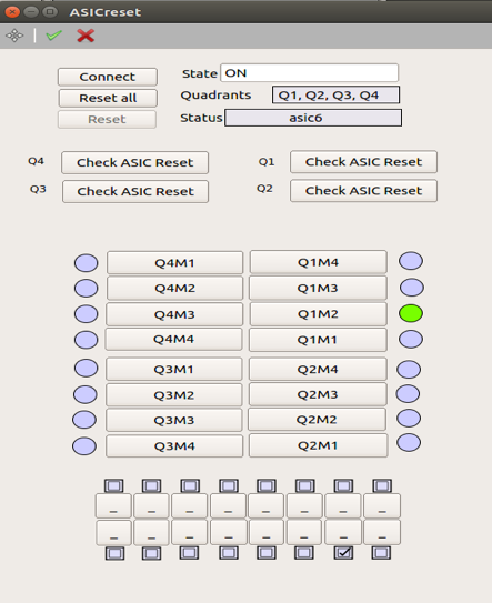
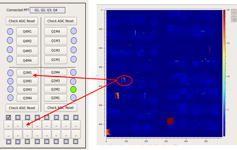
It might be that single ASICs are not recovered with this procedure. In that case, select the single ASIC on the proper ASICreset scene by selecting the proper module and ASIC number according to the map (see Fig. 4.8). By pressing the appropriate ASIC, the ASIC is reprogrammed and the flickering should disappear, however, it might be that this needs to be done more than once. If needed, press again ‘ASICs/Reset on PPT’.
4.4. Powering up the source voltages and the high voltage channels
Go back to the Automatic Power Panel scene. Switch on the source voltages by pushing the SOURCE On button. All the channels in the DSSC_Power_Status shall now go green. The online preview also changes.
To be overcautious, check from the MPOD web interface (see Table 4.1) channels 100-103, 112-115, 212-215, 200-203. All the voltages must be set to 20V. If this is not the case, call DET OCD.
Switch ON the high voltage by pushing the HV On button. All the channels in the DSSC_HV_Status shall go green, but the procedure ends only when the auto_power scene reports that DSSC is ON and the HV_Off button becomes active. Indeed, channels 100-103, 112-115, 212-215, 200-203 are switched ON to -20 V and will eventually go to -25 V in the final step.
Warning
DSSC is ON when the GUI indicates so, and when the HV Off button is active again. Error messages are reported in the GUI, please pay attention as this is a critical step for the detector.
