ALAS: The Alignment LAser System
Overview
To facilitate the alignment of the x-ray optics, apertures, drilled mirrors, diagnostics and even the sample, the alignment laser (ALAS) beam is the first beam line component in the SCS Experiment hutch. The schematics of the arrangement are shown in the top view below. The ALAS comprises a laser enclosure, an in-vacuum mirror to inject the laser beam into the X-ray beam path, and an imager to visualize overlap with the X-ray beam.
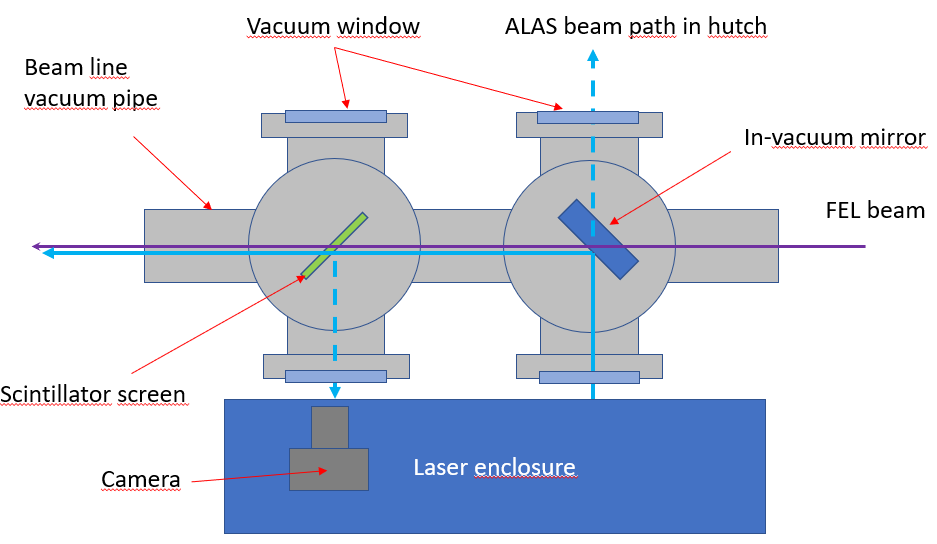
Fig. 1: Schematic of the ALAS beam line component viewed from above. The FEL beam comes from the right. The ALAS laser comes from the laser enclosure, passes through a vacuum window and bounces off an in-vacuum mirror along the rest of the beam line. An imager immediately downstream of the mirror is used to overlap the laser and FEL beams at this position. The dashed pale blue lines indicate potential paths of the ALAS laser beams
The ALAS comprises two interchangeable laser: one blue laser (473 nm) and one green laser (532 nm). Both of these laser outputs are attenuated by neutral density filters or the combination of a half waveplate and a polarizer to power levels below 1 mW, making them Class 2 lasers outside the ALAS enclosure (Class 3B inside the enclosure). Details of the laser enclosure are described in the optical layout section.
The in-vacuum mirror hangs on a pneumatic linear feedthrough that allows it to be placed on a three point mount for use, or removed from the x-ray path. The mirror blocks the x-rays so the laser and FEL beams cannot be used simultaneously. Overlap of the x-ray and ALAS beams must be achieved iteratively.
If the in-vacuum mirror is removed from the x-ray beam path, the ALAS laser beam will pass through a vacuum window into the Experiment hutch. This possibility facilitates coarse alignment of the ALAS laser. The laser beam is not hazardous, but it is undesirable to have laser beams propagating throughout the area. A suitable flange cover should always be installed over the window to block the beam.
The imager comprises a scintillator screen (CeYAG or pyrolytic boron nitride, pBN) and a camera. Details of the screens available are shown in this ELOG entry (attachment 1). The camera is located inside the laser enclosure. The screens are mounted on a motorized linear vacuum feedthrough to position them in to and remove them from the beam, as required.
The ALAS lasers reflect strongly from the polished CeYAG surface so a laser beam exits the window towards the camera. This beam reflects off the imager window and may exit the window on the opposite (-x) side. This window should always be covered by a plastic flange cap.
Optical layout
Class 3b laser beams are present inside the laser enclosure. Suitable laser safety eyewear must be worn when working inside the ALAS laser enclosure.
The optical layout inside the laser enclosure is shown schematically in Fig. 2. Fig. 3 is an annotated photograph of the installed optical setup. Either the blue or green beam can be selected by moving mirror M8 on the linear translator up (blue) or down (green). A common shutter blocks the output beam. When the green beam is in use the blue beam is blocked by the back of M8. When the blue beam is in use, the green beam is dumped onto the wall of the enclosure.
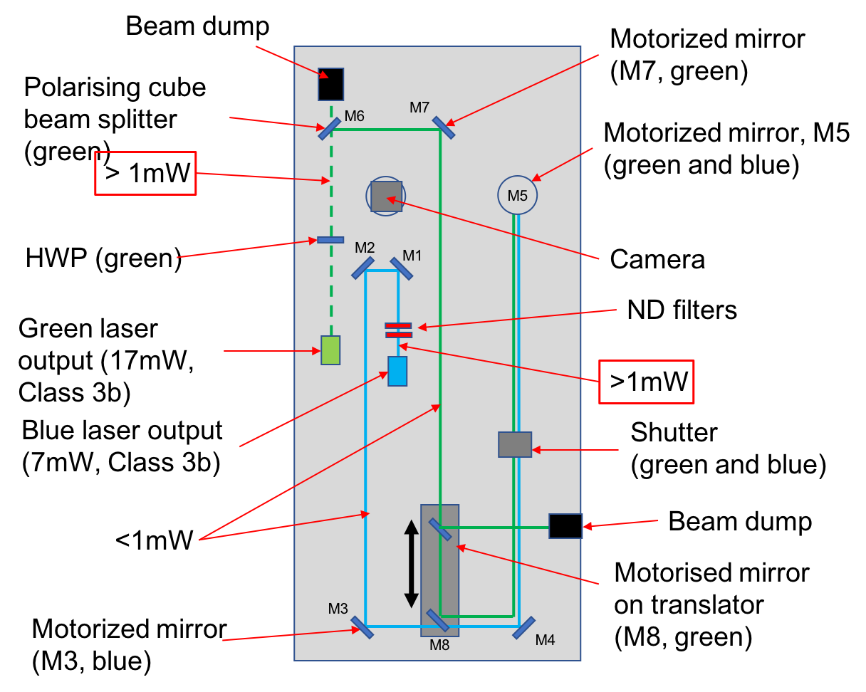
Fig. 2: Schematic of the ALAS optical layout, as of 08.03.2021. The lasers are actually fiber-coupled but the source point of the freely propagating laser beam (i.e. laser hazard) is as shown. After M8, the green and blue beams are actually collinear. The dashed green line indicates free propagation of a Class 3b laser. HWP is a half-wave plate.
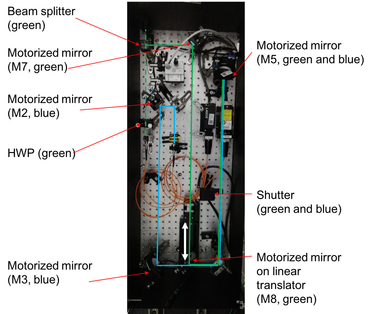
Fig. 3: The optical breadboard and laser safety enclosure of the ALAS installed at the SCS beamline as of 08.03.2021. Mirror M8 is shown in the ‘in’ position to select the green output. The laser heads and fibers (orange coils) can be seen.
Blue laser path
The blue path is shown in pale blue in Fig. 2. The laser is a BLK 7310 T from Lasos. It delivers nominally 10 mW at 473 nm. It was factory-fitted with a fiber output that reduces the available (i.e. hazardous) output to 7 mW. This is Laser Safety Class 3b. The power is reduced to <1mW by a set of neutral density filters, bringing it to Class 2.
The laser power was measured between the laser enclosure and vacuum window using a Gentec UP19K-30H-VR-D0 meter. It was not possible to measure above noise, so the power is < 1 mW.
Warning
The neutral density filters should not be removed or altered without prior consent from a Laser Safety Officer.
Green laser path
The green laser path is shown in green in Fig. 2. The laser is a ?? from Lasos. It delivers nominally 20 mW at 532 nm. It was factory-fitted with a fiber output that reduces the available (i.e. hazardous) output to about 17 mW. This is Laser Safety Class 3b. The power is reduced to <1mW by a combination of a half-wave plate and polarizing beam splitter cube (M6), bringing it to Class 2. This means that before the beam splitter, and in the rejected (vertical) path after the beam splitter, the power presents an eye hazard.
The laser power was measured between the laser enclosure and vacuum window using a Gentec UP19K-30H-VR-D0 meter and found to be < 0.3 mW.
Warning
The half-wave plate should not be adjusted without prior consent from a Laser Safety Officer.
Enclosure interlock (WIP)
The ALAS is not connected to the main laser interlock in the Experiment Hutch.
The Experiment Hutch does not need to be in laser operation mode to use the ALAS.
Daily operation
ALAS alignment
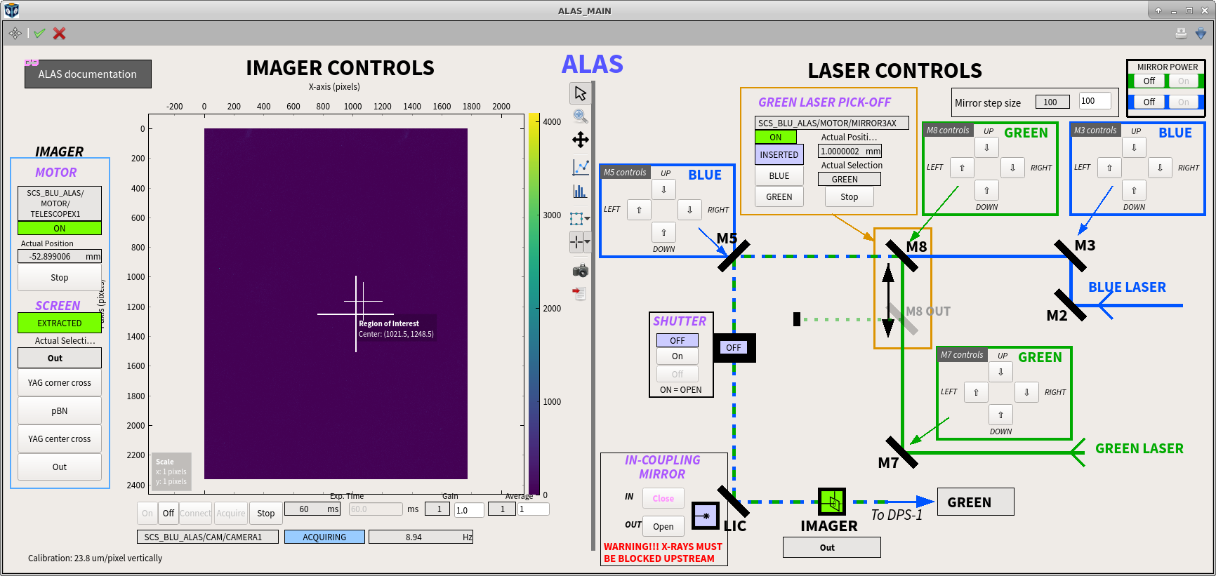
The Karabo scene to control the ALAS laser and imager is called ALAS_MAIN, a link to it is provided from the MAIN scene of the instrument. It looks like this:
ALAS Karabo scene
The left side of the scene is dedicated to the controls of the imager. There are 3 different screens available, they can be selected with the provided buttons on the left. Details of the screens are shown in this ELOG entry (attachment 1).
The right side of the scene is dedicated to the controls of the blue and green lasers. A simplified schematics (compared to this one) of the laser enclosure shows the motorized mirrors used for alignment. M3 and M5 are used to align the blue laser. M7 and M8 are used to align the green laser. These 4 motors are piezo actuators from PI, they do not have encoders and the amplitude of their movement is only controlled via the step size (top right of the Karabo scene). A step size of 100 is typical. M8 is sitting on a linear translation stage that can move in/out the green laser beam.
To switch between BLUE and GREEN:
- Close the shutter.
- Press the desired button (BLUE or GREEN) in the GREEN LASER PICK-OFF box.
- Wait until the actual selection is the one desired.
- Open the shutter.
To align the ALAS beam:
- Block the X-ray beam upstream.
- Insert the in-coupling mirror.
- Insert the imager screen (usually YAG center cross, or pBN).
- Select which laser to use in the PICK-OFF GREEN MIRROR box.
- Open the shutter (ON is open / OFF is closed). You should now be able to see the ALAS on the ALAS imager.
- Adjust the step size of the piezo motors (top right of the scene).
- Use M3 to steer the BLUE beam or M7 to steer the GREEN beam on the ALAS imager.
- Remove the ALAS imager
- Use M5 to steer the BLUE beam or M8 to steer the GREEN beam on an imager downstream.
- Insert the ALAS imager back and check alignment.
- Repeat 7 - 10 until the beam is well centered on both imagers.
Once the alignment is finished:
- Close the shutter.
- Remove the imager.
- Remove the in-coupling mirror.
Troubleshooting
Problem: The controls of the piezo mirrors are not instantiated
Solution:
- Check in the SCS_BLU_ALAS project that the middlelayerServer/alas1 (see screenshot) is up and running. If not, try power cycling using the Mirror Power ON/OFF buttons (top right of the ALAS_MAIN scene).
- Once the server alas1 is up and running, instantiate all devices.
- By default, the motors have no step size and will not move upon request. Change the step size in the Mirror step size field of the ALAS_MAIN scene.
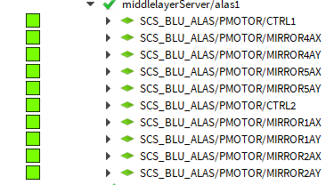
Middlelayer server that controls the piezo motors
Problem: The Mirror step size field is broken
Solution: In the SCS_BLU_ALAS project, instanciate the macro SCS_BLU_ALAS/ALAS_MIRROS_STEP.
Motors and Karabo connections
| Mirror on bread board | Karabo name |
|---|---|
| M3 H | MIRROR2AX |
| M3 V | MIRROR2AY |
| M5 H | MIRROR5AX |
| M5 V | MIRROR5AY |
| M7 H | MIRROR1AY |
| M7 V | MIRROR1AX |
| M8 H | MIRROR4AY |
| M8 V | MIRROR4AX |