Digitizers
We currently have 4 digitizers: 2x Fast ADC (SIS8300) and 2x ADQ 412. The second ADQ 412 has not yet been tested and added to the DAQ. They are all located in the rack room. EEE has some documentation on these digitizers on Alfresco.
| Type | uTCA | Karabo name | Trigger device |
|---|---|---|---|
| Fast ADC | 1 | SCS_UTC1_MCP/ADC/1 | SCS_RR_UTC/TSYS/FAST_ADC |
| ADQ 412 | 1 | SCS_UTC1_ADQ/ADC/1 | SCS_RR_UTC/TSYS/ADQ412 |
| Fast ADC | 2 | SCS_UTC2_FADC/ADC/1 | SCS_RR_UTC2/TSYS/FAST_ADC |
| ADQ 412 | 2 | SCS_UTC2_ADQ/ADC/1 | SCS_RR_UTC2/TSYS/ADQ412 |
Note
The Fast ADC channels 2 to 9 are equipped with an RTM strecher to allow the visualization of short signals in the nanosecond range. Channels 0 and 1 do not have this strecher.
PPG port connections
The patch panels (PPG) host SMA ports for coaxial connections between different parts of the SASE 3 area (see Map of the XHQ SASE 3 area to locate the PPGs). PPG 210 is a newly installed PPG in the ILH and is not on the map.
The following table shows the connections between the digitizer channels and the rack room ports, in the rack room. It must be updated when a connection is modified.
| Digitizer channel | Rack Room port | Last updated |
|---|---|---|
| FastADC 0 | 1306 | 2022.08.15 |
| FastADC 1 | 1318 | 2022.08.15 |
| FastADC 2 | 1308 | 2022.08.15 |
| FastADC 3 | 1307 | 2022.08.15 |
| FastADC 4 | 4 | 2022.08.15 |
| FastADC 5 | 1315 | 2022.08.15 |
| FastADC 6 | 1 | 2022.08.15 |
| FastADC 7 | 2 | 2022.08.15 |
| FastADC 8 | 3 | 2022.08.15 |
| FastADC 9 | 1310 | 2022.08.15 |
| ADQ412 1A | 1314 | 2022.05.20 |
| ADQ412 1B | 1313 | 2022.05.20 |
| ADQ412 1C | 1312 | 2022.05.20 |
| ADQ412 1D | 1311 | 2022.05.20 |
This table shows how a device is connected to a digitizer channel. It must be updated when a connection is modified.
| Device | Connections [PPG/Port] | digitizer |
|---|---|---|
| TIM MCP1 | 202b/1311 -> RR/1311 | ADQ412 1A |
| TIM MCP2 | 202b/1312 -> RR/1312 | ADQ412 1B |
| TIM MCP3 | ||
| TIM MCP4 | ||
| FFT MCP Fluo | 202b/1311 -> RR/1311 | ADQ412 1D |
| FFT Reflect. PD | 202b/1309 -> RR/1309 | FastADC 3 |
| ILH SHG setup PM | 202b/1318 -> RR/1318 | FastADC 1 |
| FFT Diag. PD 1 | 202b/1310 -> RR/1310 | FastADC 4 |
| FFT PD for PP Io | 202b/1317 -> RR/1317 | FastADC 9 |
| ILH PP 800 nm Io | 206/1332 -> 202b/1332 -> 202b/1315 -> RR/1315 | FastADC 5 |
| ILH AFS Io | 206/1331 -> 202b/1331 -> 202b/1308 -> RR/1308 | FastADC 2 |
| ILH TOPAS Io | 206/1333 -> 202b/1333 -> 202b/1306 -> RR/1306 | FastADC 6 |
| ILH SHG setup PD1 | 210/1 -> RR/1 | FastADC 0 |
| ILH SHG setup PD2 | 210/2 -> RR/2 | FastADC 7 |
| ILH SHG setup PD3 | 210/3 -> RR/3 | FastADC 8 |
SMA ports location
This table shows the location of the two SMA ends of coaxial cables.
| Port | Patch Panel 1 | Patch Panel 2 |
|---|---|---|
| 1301 | PPG 201 | Rack Room |
| 1302 | PPG 201 | Rack Room |
| 1303 | PPG 201 | Rack Room |
| 1304 | PPG 201 | Rack Room |
| 1305 | PPG 202b | Rack Room |
| 1306 | PPG 202b | Rack Room |
| 1307 | PPG 202b | Rack Room |
| 1308 | PPG 202b | Rack Room |
| 1309 | PPG 202b | Rack Room |
| 1310 | PPG 202b | Rack Room |
| 1311 | PPG 202b | Rack Room |
| 1312 | PPG 202b | Rack Room |
| 1313 | PPG 202b | Rack Room |
| 1314 | PPG 202b | Rack Room |
| 1315 | PPG 202b | Rack Room |
| 1316 | PPG 202b | Rack Room |
| 1317 | PPG 202b | Rack Room |
| 1318 | PPG 202b | Rack Room |
| 1319 | E0.05 PPG 207 | PPG 202b |
| 1320 | E0.05 PPG 207 | PPG 202b |
| 1321 | E0.05 PPG 207 | PPG 202b |
| 1322 | E0.05 PPG 207 | PPG 202b |
| 1323 | E0.05 PPG 207 | PPG 202b |
| 1324 | E0.05 PPG 207 | PPG 202b |
| 1325 | E0.05 PPG 207 | PPG 202b |
| 1326 | E0.05 PPG 207 | PPG 202b |
| 1327 | E0.05 PPG 207 | PPG 202b |
| 1328 | E0.05 PPG 207 | PPG 202b |
| 1329 | E0.05 PPG 207 | PPG 202b |
| 1330 | E0.05 PPG 207 | PPG 202b |
| 1331 | ILH PPG 206 | PPG 202b |
| 1332 | ILH PPG 206 | PPG 202b |
| 1333 | ILH PPG 206 | PPG 202b |
| 1334 | ILH PPG 206 | PPG 202b |
| 1335 | ||
| 1336 | ||
| 1337 | ||
| 1338 | ||
| 1 | ILH PPG 210 | Rack Room |
| 2 | ILH PPG 210 | Rack Room |
| 3 | ILH PPG 210 | Rack Room |
| 4 | ILH PPG 210 | Rack Room |
| 5 | ILH PPG 210 | Rack Room |
| 6 | ILH PPG 210 | Rack Room |
| 7 | ILH PPG 210 | Rack Room |
| 8 | ILH PPG 210 | Rack Room |
| 9 | ILH PPG 210 | Rack Room |
| 10 | ILH PPG 210 | Rack Room |
| 11 | ILH PPG 210 | Rack Room |
| 12 | ILH PPG 210 | Rack Room |
| 13 | ILH PPG 210 | Rack Room |
| 14 | ILH PPG 210 | Rack Room |
| 15 | ILH PPG 210 | Rack Room |
| 16 | ILH PPG 210 | Rack Room |
Updating the channel description
Each channel of the Fast ADC has a parameter ‘Signal description’ that can be used to indicate which device it is connected to. This property has the advantage of being saved in the DAQ.
Upon change of connections, one should follow the procedure below (click on the animation for better resolution) to make sure that the channel’s signal description is properly updated.
- Stop acquisition
- Edit text fields
- Start acquisition
- Navigate to the FADC Karabo device
- Right click + Store online configuration
- Save project
Example of how to update and save the channel signal description of the Fast ADC. The I0 PD of the PPL was exchanged from channel 2 to channel 0 of Fast ADC 1.
Peak integration (APD) parameters of the ADQ412
The peak integration parameters (historically called APD) can be set to calculate the intensity of peaks (MCP signal, for instance) in a raw trace. Baseline subtraction relative to each peak is applied. For each channel, the parameters to set are the starting sample Pulse Begin, the ending sample Pulse End, the baseline starting sample Base Begin, the baseline ending sample Base End, the Initial Delay which is equal to the Pulse Begin, and the Upper Limit which is equal to the Pulse Begin + period. The number of pulses is set for all channels via the property Pulses per trigger.
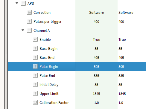
APD parameters of the ADQ412 Karabo device, under the node Board 1.
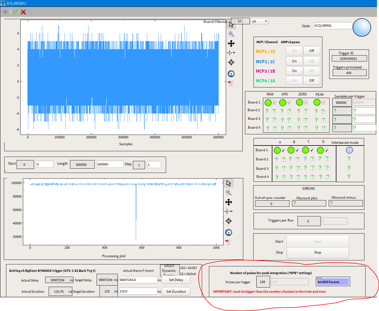
Up to now, these parameters must be set manually for all channels and do not update upon changes of FEL parameters (rep. rate, number of pulses…). Therefore, we set them once to record many pulses at a high repetition rate - to make sure all pulses are caught - and do not update upon change of FEL parameters. The SCS Toolbox can then figure out which pulses from the APD array actually contain signal, based on the pulse pattern of the machine. In any case, we also record the raw trace, in case an error with the APD settings occurs.
For convenience, we have a macro that updates the APD parameters of all channels at once. The macro is called SetAPDParameters in the SCS_DIGITIZERS project. Make sure that the macro is running. A link to the scene of the macro can be found in the main scene of the ADQ412:
For convenience, the macro has a parameter period instead of the Pulse Begin and Upper Limit properties of the ADQ412. The ADQ412 has a sampling rate of 2 GHz, which translates to 440 samples per XFEL pulse at 4.5 MHz. The period must therefore be a multiple of 440. At 1.1 MHz, the period is 440*4 = 1760 samples.
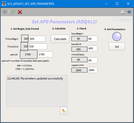
- Set the period based on the maximum repetition rate that will be used during the run period.
- Once signal is found on the raw trace, zoom in on the first pulse and determine the starting and ending samples (Pulse Start and Pulse End).
- Click on Calculate, it will automatically determine the baseline settings, using baseBegin = Pulse Begin - 420 and baseEnd = Pulse Begin - 10. You can always update these values if the so-defined baseline is not suitable.
- Make sure the digitizer is not acquiring.
- Click on Set when ready. It can take a few seconds until the parameters are updated. A status notification indicates when it is done.
- Finally, in the main ADQ412 scene, set the number of pulses to record. This number of pulses must be chosen in accordance with the period, to have a large enough time window. Typically, 400 pulses with a period of 1760 (1.1 MHz) gives ~350 microsecond time window.