Starting operation with grating in zeroth/first order
with 13 mrad mirror offset
When you come to the control room, there likely will be no beam, the mirrors and monochromator grating and pre-mirror may be realigned.
If you need to start the Karabo:
Ideally, there is a Karabo GUI icon on the desktop or in the menu. If not:
open terminal (for example right click on a screen and “Open Terminal”)
type in the terminal:
cd
cd karabo
source activate
karabo-gui
Karabo projects that you may need:
- SA3_MAIN
- (hostname sa3-br-con-gui1:44444) controls the things in SASE3 photon tunnel
- SA3_MIRROR_SWITCH
- (hostname sa3-br-con-gui1:44444) for the automatic alignment of the most important mirror parameters in the tunnel
- MAIN
- (hostname scs-rr-sys-con-gui1:44444) controls the things in SCS hutch
If you need to start jddd
(DOOCS, control of accelerator, undulators, triggers, etc.):
open terminal
type in the terminal:
ssh yourusername@exflgateway
javaws /opt/karabo/jddd-run.jnlp
in java svn browser: open XFEL/MainTaskbar/XFELMainTaskbar.xml
purple start screen appears. Click on Status button
in status screen click on public status Display
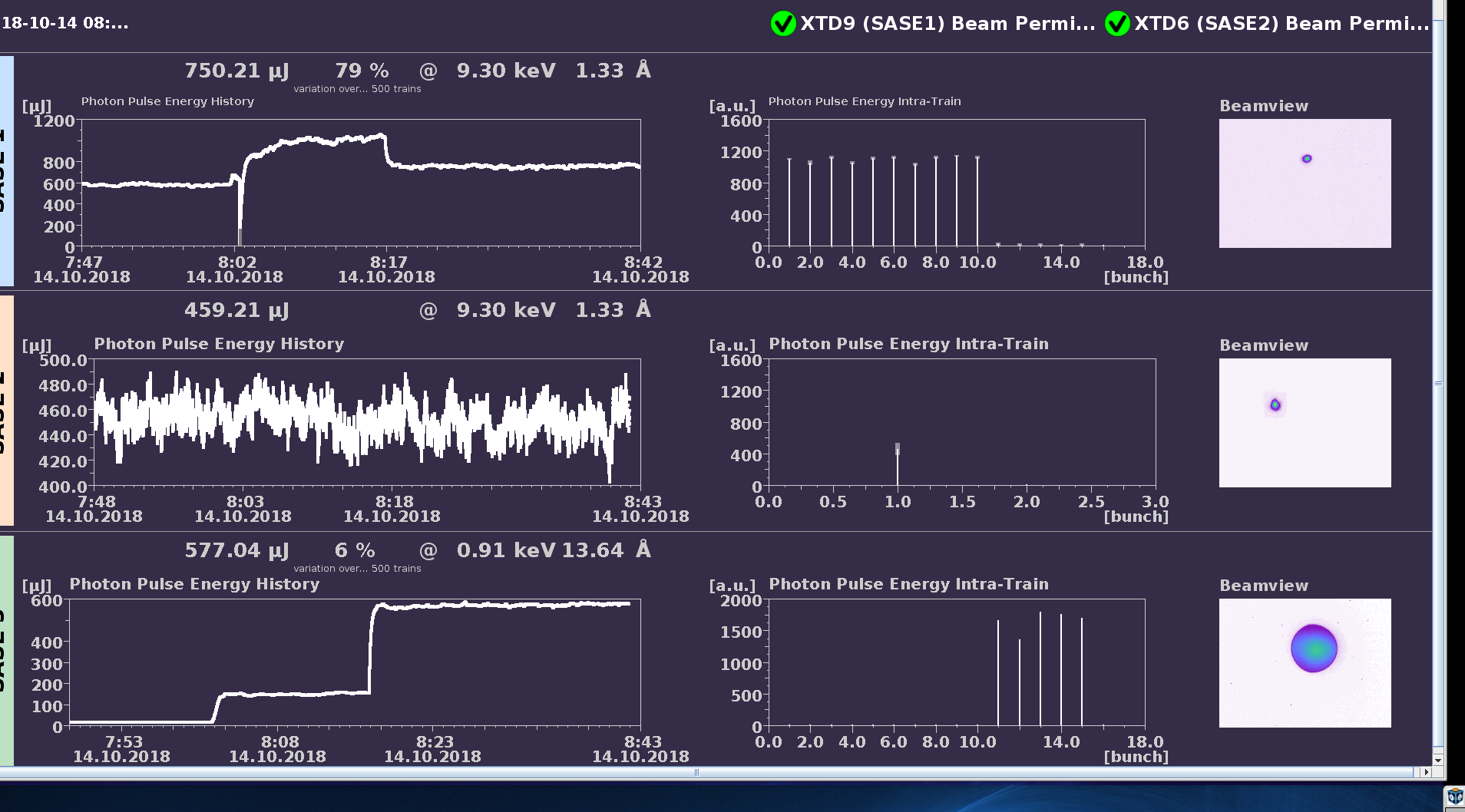
for pulse energy details, click on Photons button of main screen
click XGMD Overview button
choose SASE3/XTD10 tab at top of screen and click SASE Viewer on the left side
Step-by-step manual how to start the SCS operation
Make sure that the pressure in gas attenuator in the tunnel (GATT) is > 2 mbar. This is a condition to have the beam shutters of SCS and SQS closed.
Now you need to move the mirrors M1, M2, M5, grating and mono pre-mirror (PM) into the positions required for the regime of SCS operation with grating in 0th or 1st order with mirror offset 13 mrad. You will require two scenes for this:
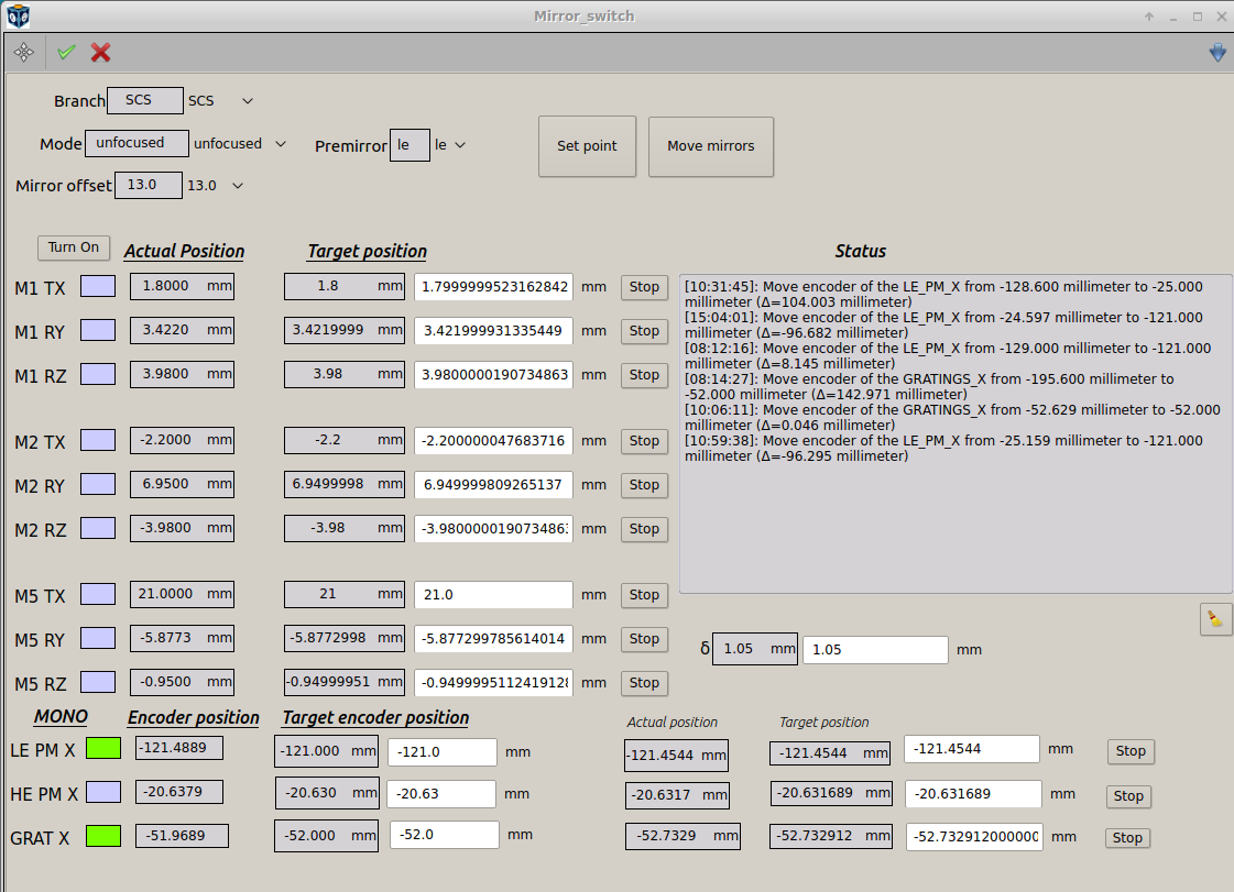
- the scene “Mirror_switch” in Karabo project SA3_MIRROR_SWITCH - controls the settings of mirrors M1, M2, M5 and monochromator.
- the scene “SA3_BRANCH_CONFIG” opened by clicking the button “Branch-Config” in the main diagram of SASE3 in the Karabo project “SA3_MAIN” - controls the setting of monochromator to tune it to the 0th/1st order and specific photon energy.
We assume that the monochromator is set to zeroth order in the beginning: in the scene “SA3_BRANCH_CONFIG” the “Diffraction order” is set to 0.
First, open the scene “Mirror_switch” and in the top part of it set the following:
- Branch: SCS
- Mode: grating
- Mirror offset: 13
- Premirror: le
- click on green arrow
- click “Set point”
- click “Move”
Second, go to the scene “SA3_BRANCH_CONFIG” and choose: - Mirror offset: 13 - Branch: SCS - Monchromator mode: Grating - Click on «Configure Monochromator“ - diffraction order: 0 (to later check the position of the beam at the
SCS PopIn)
- selected mirror: low energy
- target energy: according to the energy in doocs panel
- click „Move“, once the movement is complete click a second time because it is a long movement and it helps to get a better accuracy
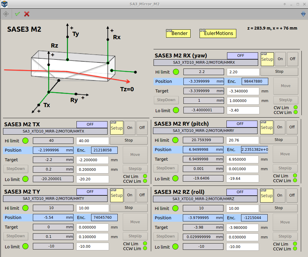
Third, M2 bender (click Bender in the window “SASE3_Mirror_M2” of the project SA3_MAIN): set it 57.8 deg (it might be optimized later, this value comes from operation with first 8 undulators closed).
The monochromator is now set to the zeroth order. If you need to switch to the first order, please, do the next steps, and in paragraph 11) the switching procedure is given.
It might take quite a long time for the positions M5 TX and MONO GRAT X to change after setting, because SQS uses very different values and they change slowly.
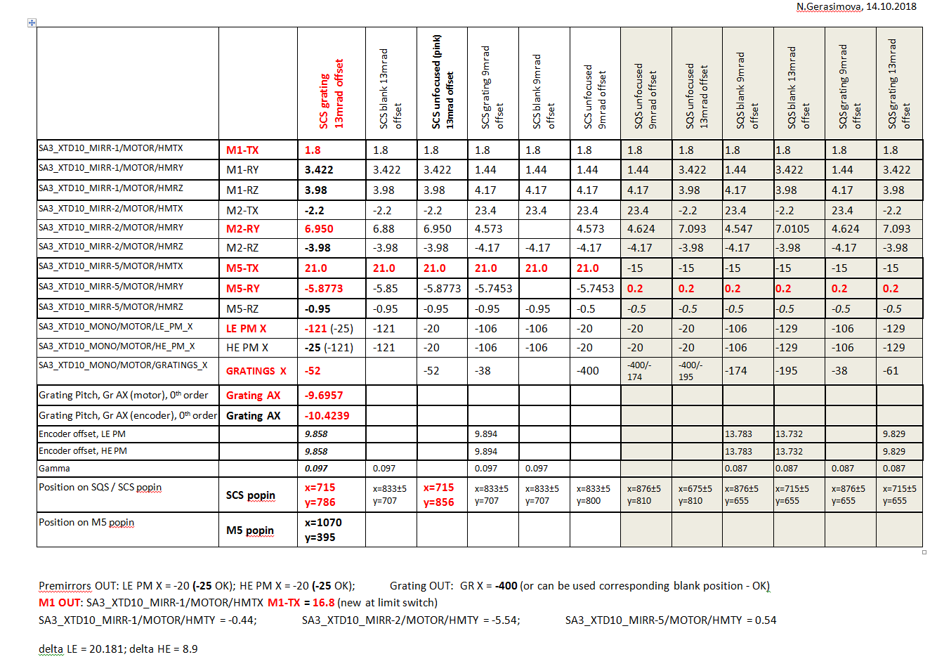
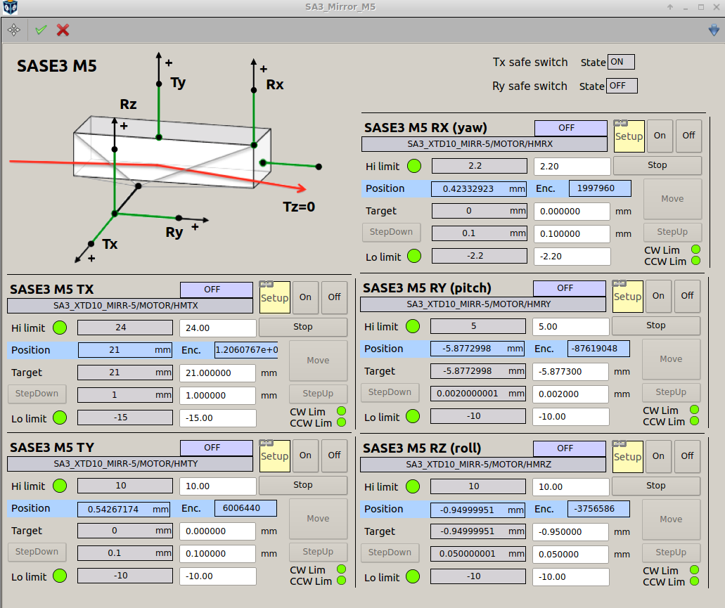
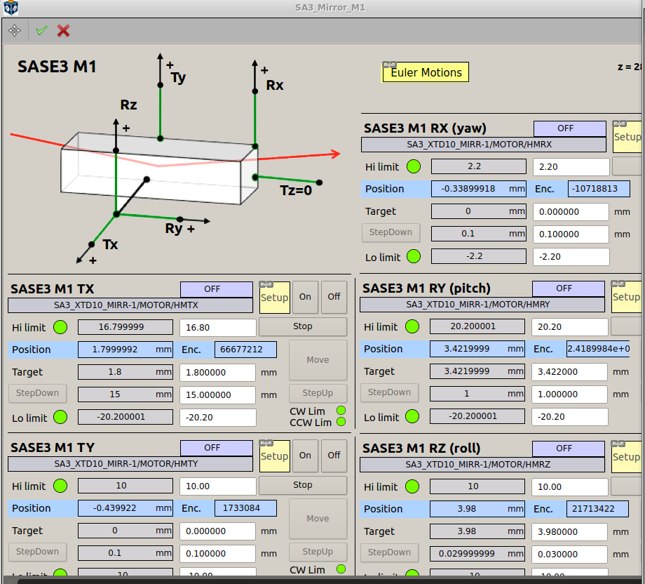
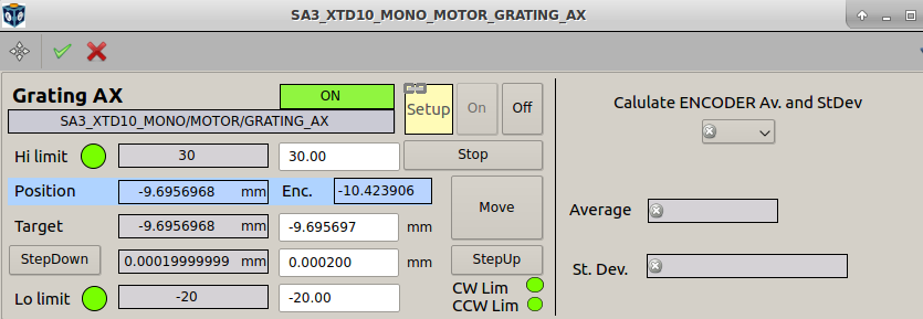
You may also check the parameters manually in the windows “SA3_Mirror_M1” (M2, M5) and “SA3_XTD10_MONO_MOTOR_GRATING_AX” according to the list below (given for the 0th order), the table (the column “SCS grating 13mrad offset”) and the screenshots:
- M5 TX: 21 mm - distribution mirror to SCS
- M5 RY (pitch): -5.8772998 mm
- M5 RZ (roll): -0.95 mm
- M2 TX: -2.2 mm
- M2 RY (pitch): 6.9499998 mm
- M2 RZ (roll): -3.98 mm
- M2 bender: 57.8 deg
- M1 TX: 1.8 mm
- M1 RY (pitch): 3.422 mm
- M1 RZ (roll): 3.98 mm
- Grating AX (pitch): motor ≈ -9.6957 mm; encoder (important) -10.4239 mm
- MONO LE PM X encoder position: -121.0 mm (low energy pre-mirror in)
- MONO HE PM X encoder position: -21 mm (high energy pre-mirror out)
- MONO GRAT X encoder position: -52 mm (mono grating in)
search the hutch and open the shutter.
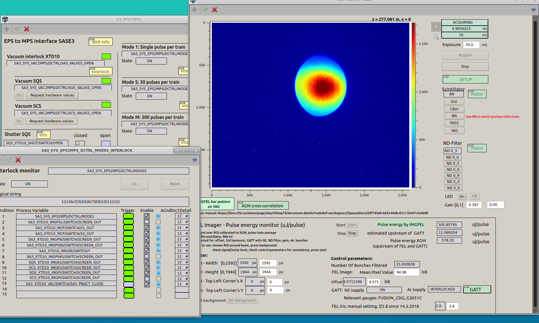
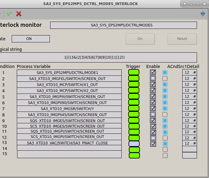
remove the interlocks for the imagers in tunnel by clicking the blue squares in the window “SA3_SYS_EPS2MPS_DCTRL_MODES_INTERLOCK” (the screenshot below):
- SA3_XTD10_IMGFEL (SASE3 FEL imager)
- SA3_XTD10_IMGPII45 (M5 mirror imager)
- SCS_XTD10_IMGPI (SCS Pop-in imager)
- click the green arrow
Call BKR (4500), ask for the beam: 5 pulses in a bunch or so.
Put the FEL imager SA3_XTD10_IMGFEL in, use the BN screen. If the beam is not centered in the FEL imager, call BKR and ask them to center it in the aperture.
At some moment the mirrors will move into the required positions, including the distribution mirror M5, and in the SASE3 diagram the circle “SQS beam possible” will turn off - become blue-gray and “SCS beam possible” will turn on - become green.
Important
now in the window with MPS safety rectangles (see the figure below, the left one) the “Pressure > 2 mbar” will be green; the beam “Disabled by M5” will become green for SQS and blue-gray for SCS; “Shutter Open” will be blue-gray for SQS and green for SCS. It means that SCS can now take the beam without damaging the beam shutter. Only now you can start pumping the GATT to increase the beam intensity!
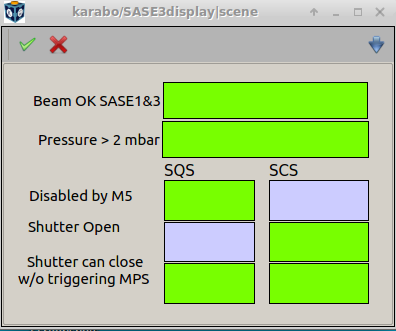
This is when you can start pumping out the gas from GATT to work at SCS: - the pressure in GATT is > 2 mbar; - the mirror M5 brings the beam to SCS and blocks for SQS; - the shutter is open for SCS.
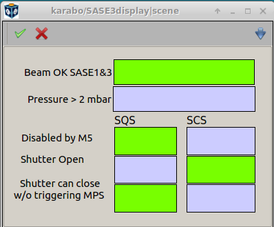
This is when you can start working with beam at SCS because the gas pressure in GATT is < 2 mbar.
Start changing the pressure in GATT step-by-step to ≈ 1.5, 1.0, 0.8, 0.7, 0.6, 0.5 mbar. The rectangles in the MPS safety window will switch the color like in the figure above, the right one. Watch how the beam appears in the FEL imager. If you don’t see the beam appearing normally in the center of aperture (6 mm), call BKR again and ask to adjust the beam.
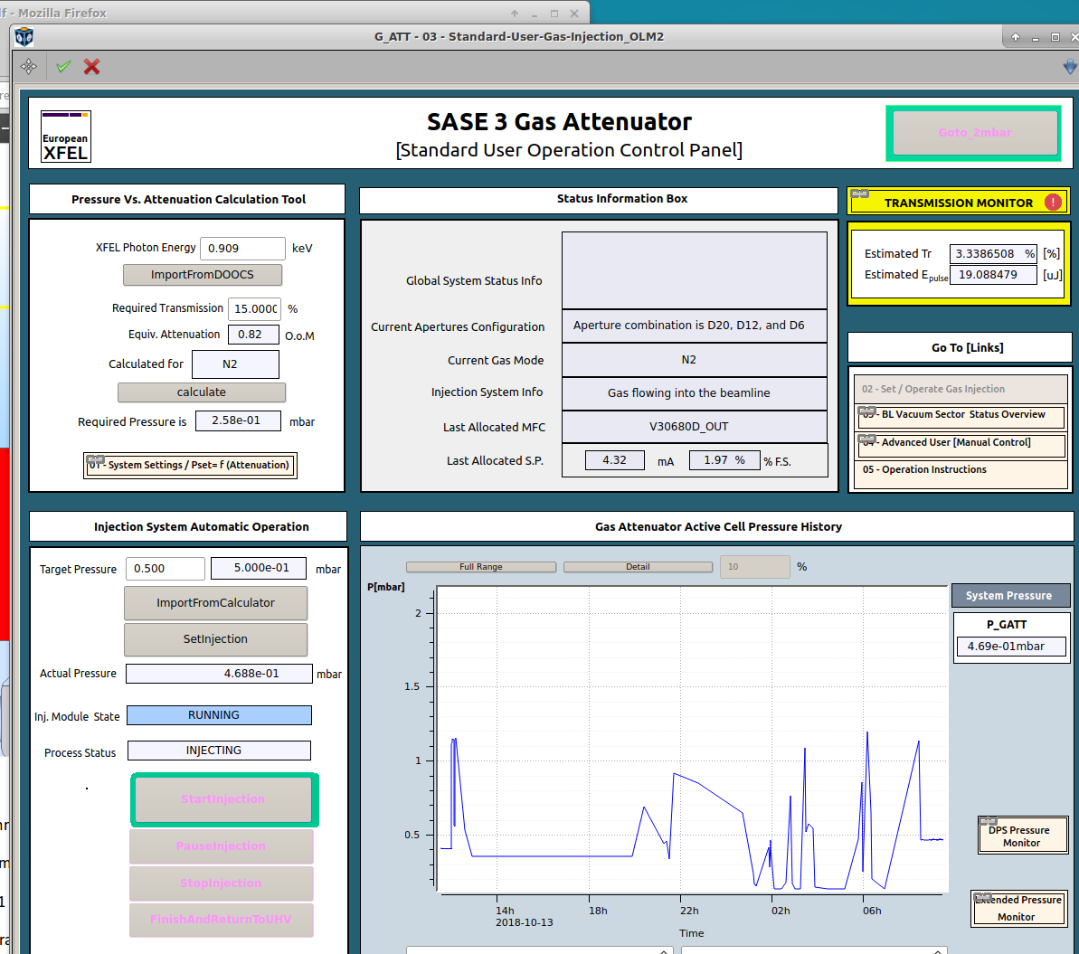
Finally, set the GATT pressure to ≈ 0.5 mbar so that the transmission will be ≈ 3% (see the screenshot below). It is enough to safely work with imagers (at least for the beam with 5 pulses of 1.8 mJ, like in our example). Congratulations, now you are ready to work with beam at SCS!
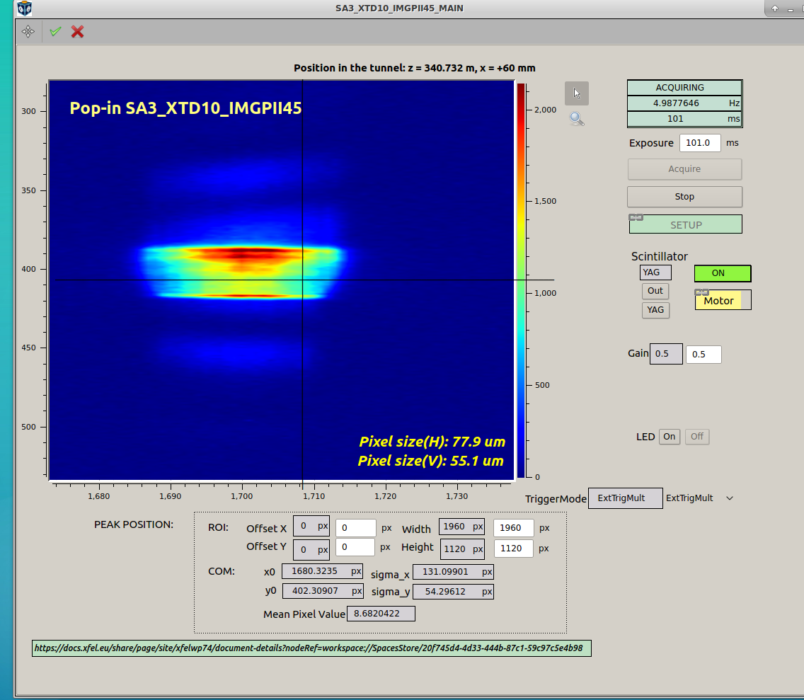
Put the imagers SA3_XTD10_IMGPII45 (M5 mirror imager) and SCS_XTD10_IMGPI (SCS Pop-in imager) in, check your beam. You should see something like this:
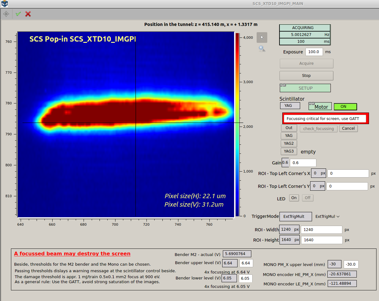
In the SCS Pop-in imager the position of the beam should be x ≈ 715, y ≈ 786.
switching to the first order of monochromator
Now, if you wish to switch to the first order of the grating, in the scene “SA3_BRANCH_CONFIG” set the required photon energy in the field Target energy (before this look at the photon energy produced by undulator), set the “Diffraction order” to 1 and click “Move”. The monochromator grating will automatically move to the correct position.
Setting of the slits
In case of both 0th and 1st order operation you need to check the SRA (spontaneous radiation aperture), vertical slits and exit slits.
- In the “SA3_MAIN” diagram click on “SRA”, the scene “SASE3_SRA” will open. You need to check that the Gap Y center is set to -0.6 and size set to 2 mm. This will center the beam to the center of the grating and the grating open aperture in the 0th order.
- In the “SA3_MAIN” diagram click on “Vertical Slit” to open the scene “SASE3_VSLIT”. Set the “Gap Y” center to -0.7. This will center the beam to the center of the grating. The gap of vertical slits that fits the grating open aperture in the 0th order is 3.2 mm, the minimum size of the gap should be 0.4 mm. The gap for the first order of the grating is slightly smaller but can be neglected.
- Open the exit slits scene “ESLIT”. In the 0th order of the grating it should be 0.6 mm (in operation) and 2 mm (for alignment). For the 1st order it should be 0.3 mm.
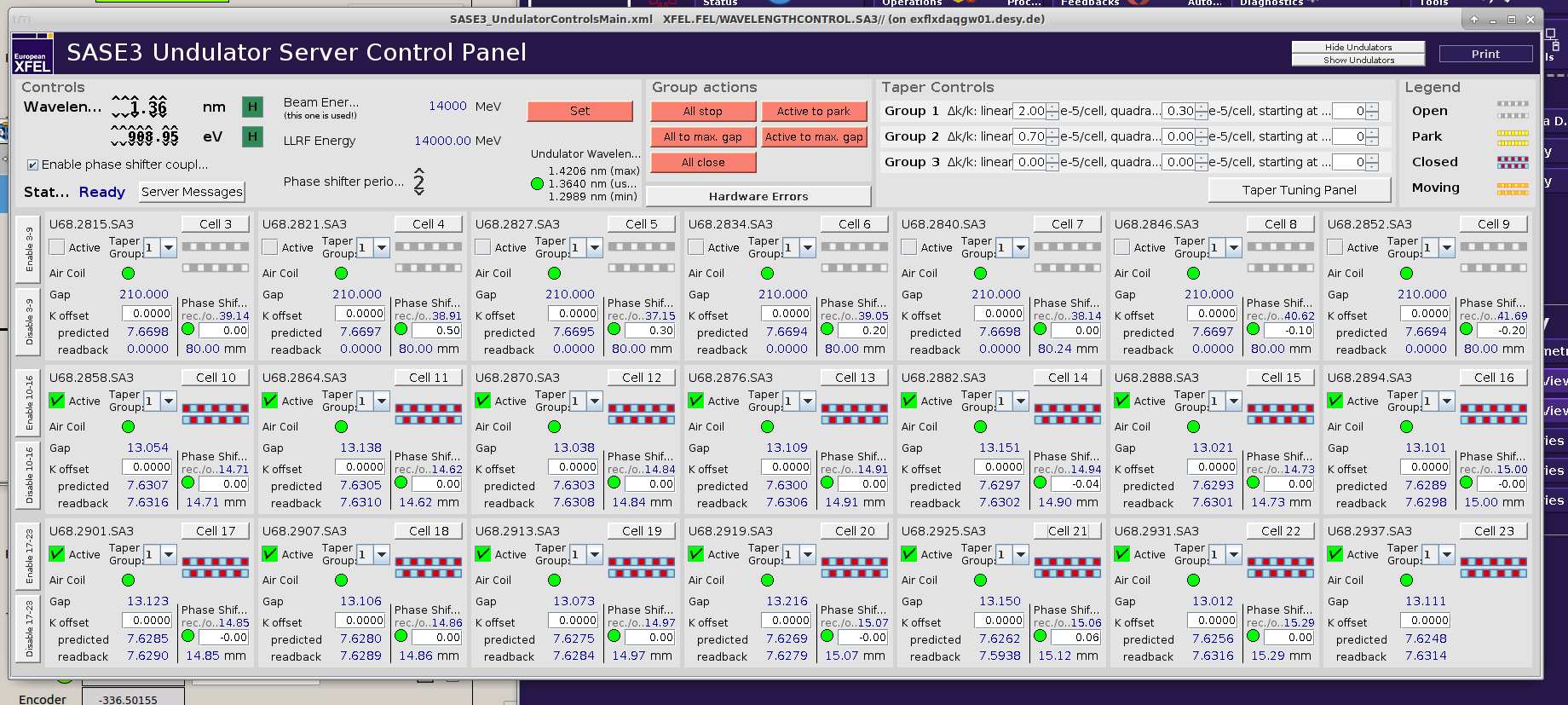
Make the screenshot of the windows with SASE3 FEL imager, M5 mirror imager, SCS Pop-in imager, parameters of the mirrors M1, M2, M2 bender and M5, grating, SASE3 interlocks, XFEL beam status and SASE3 undulator status, put it in the Elog as Commissioning – General – Beam Alignment, call it something like “Status at startup”, write the number of pulses and pulse energy in the Elog post.