FFT Airpad Operation
(Cleanroom location with Compressor)
For Short List of Tasks see short list.
Technical precondition
Operation of the Airpads on the FFT needs mostly high massflow of compressed air, but not that much of pressure. Supply of air which is spread through XHQ does not qualify for that.

Therefore XFEL provides a Roots compressor. The compressor is shared with other WP’s, it may be located somewhere in XHQ. Unfortunately it is not bookable in Zimbra calender, so you have to plan its usage in foresight.

- For operation of the compressor you need a briefing by the Technical Service Group (TS)
- For start of operation after placing the compressor you need an acceptance check by the Safety Group.
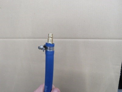
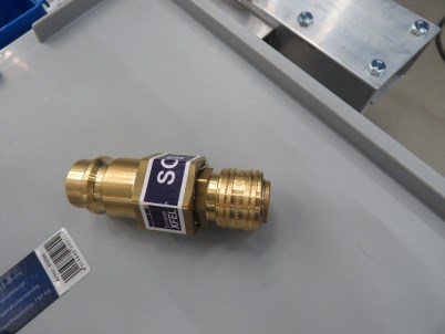
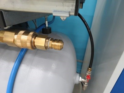
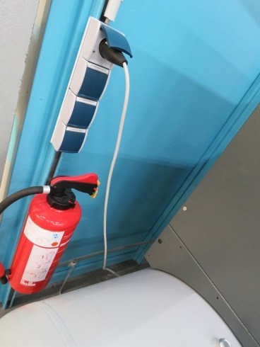
By now the airpad supply-hose is equipped with a size7 connector, the compressor do have a Size19 connector outlet. In case there is no reducer already plugged in, SCS do has luckily its own.
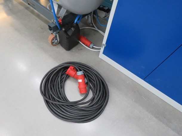
The compressor needs 380 V with CEE Type 30 A connector. If the one 30 A outlet on the pillar near the SCS cleanroom area is blocked, the extension cord is mandatory and by now there is a orange supply cabinet nearby behind the TS-storage-area to connect to.


Also the cooler/dehumidifier needs to be plugged in 230 V, what mostly can be found nearby the SCS area.
Operation of Pads by the regulators
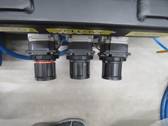
The three airpads are operated manually by three rotational regulators. They are secured against adjustment by pushing the handle with a click towards the gauge.
To have them in adjustable position the need to be slightly pulled with a click, then an orange ring indicates the unlocked position.

When operation before was done proper, they should be closed and with running compressor or awaiting pressure on the supply hose the gauges show zero pressure.
To raise the pressure and the airflow through the pads the regulator “knob” needs to be turned right (it screws in, towards the regulation membrane). Thus means lowering pressure and airflow up to being shut it needs to be turned left. Due to recent experiences the maximum pressure that will arise when all three pads are full in operation is 2 bar on the gauges.
Each gauge/regulator is labelled with respect to the corner of the pad that it’s operating. In those corners are the motor driven gears of the instrument are located and painted in the given color, this helps indicating which corner of the frame to rise/lower.


During operation it may cause due to the different setups with center of mass, that one pad needs to be lowered after its support block is removed, to help one of the other pads with some extra rising to free its support block. This needs to be communicated constantly between the persons doing the duty to prevent injuries and damages.
Safety Hints
- Minimum 2 persons are demanded for safe operation.
- Person2 check not to lose your helmet when operating the support blocks.
- Person2 check not to have your DACHS waving on a long line from your neck in front of your face when operating the support blocks.
- Check if the lane to the designated location for the FFT is free and won’t get blocked during operation, and that the lane is technically accessible for the pads.
- Remove loose items from FFT, disconnect really all cables and hoses if necessary.
- Follow local Safety Rules from XFEL
Short Procedure for Operations
Preconditions
- Person1+2: Place compressor and get safety acceptance
- Person1 or 2: Connect compressor as taught by TS group
- Person1 or 2: Connect hose from FFT to compressor
- Person 2: Get prepared to grab the support blocks
- Person 1: Check if regulators on FFT are shut
(Technically it does not matter if handlebar valve on FFT and compressor are shut or open, or mixed. Difference is just up to where the pressure already is lead. But it’s not wrong to have both closed)
Operation
- Person1: Start Compressor and cooler/humidifier as taught by TS Group and wait for stable condition
- Person1: Open handlebar valves on compressor and FFT in random order
- Person1: Start opening the regulators until lifting of component is visible, tell Person2 constantly on which regulator you’re doing which move. Tell which one you’re willing to operate and him to remove supportblock from.
- Person2: Tell Person1 constantly if the support blocks are freed and when to stop the corresponding regulator. Remove support block and wait for further instruction.
- Person1: When all blocks are removed check for alignment of the FFT that nothing is touching the floor by adjusting the regulators.
- Person1+2: Move the FFT to your desired location, Person1: check for free space regarding the hose and give constant feedback to Person2.
FFT In Place
Same procedure backwards, for the first block it may be difficult to aim due to the lightly movement of the FFT, be careful and don’t rush. For 2nd and 3rd block it’s then more easily.
- Person1: When done switch off compressor as taught by TS and let all buffered air out through the pads, then close handlebars and regulators, remove hose.
- When done for the day, remove extension cord from the floor.