Load Lock

Drawing of the load lock transfer system. From Sketch File.
Venting and pumping down the Transfer Load Lock system
Venting
Make sure the gate valve between the FFT and the Load Lock is closed.
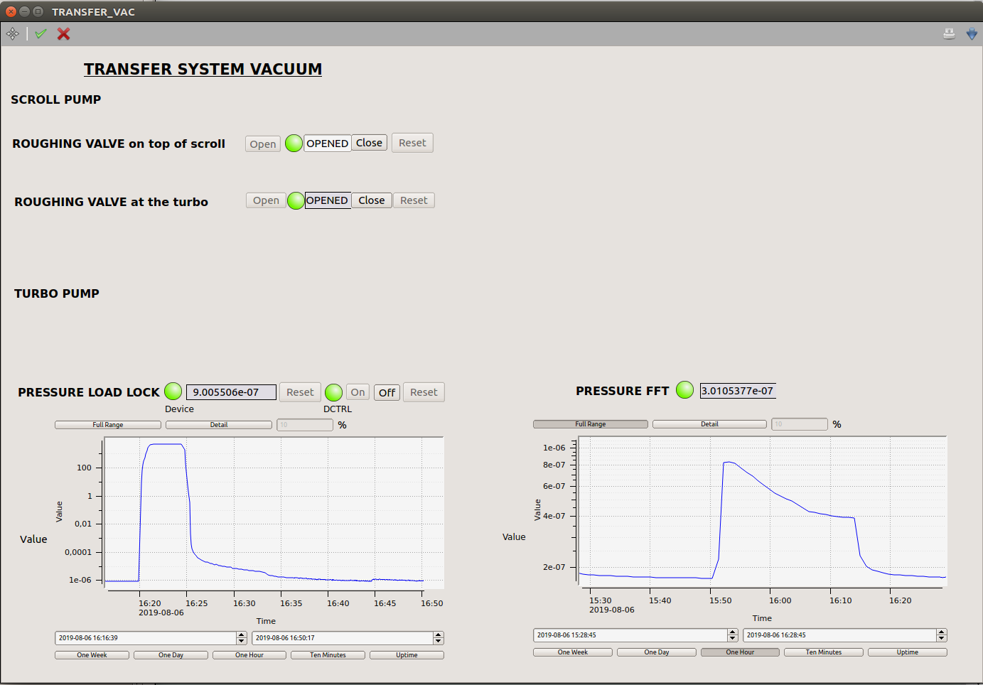
If a fast pumping down is acceptable, one can close the roughing valve at the turbo in the TRANSFER_VAC scene from LOOP11.
If a slow pumping down is necessary, one must close the roughing valve on top of scroll pump in the TRANSFER_VAC scene from LOOP11 and leave the other roughing valve open so has to vent a large volume.
Then switch off the turbo pump at the controller on the floor in front of the LIN-DPS.
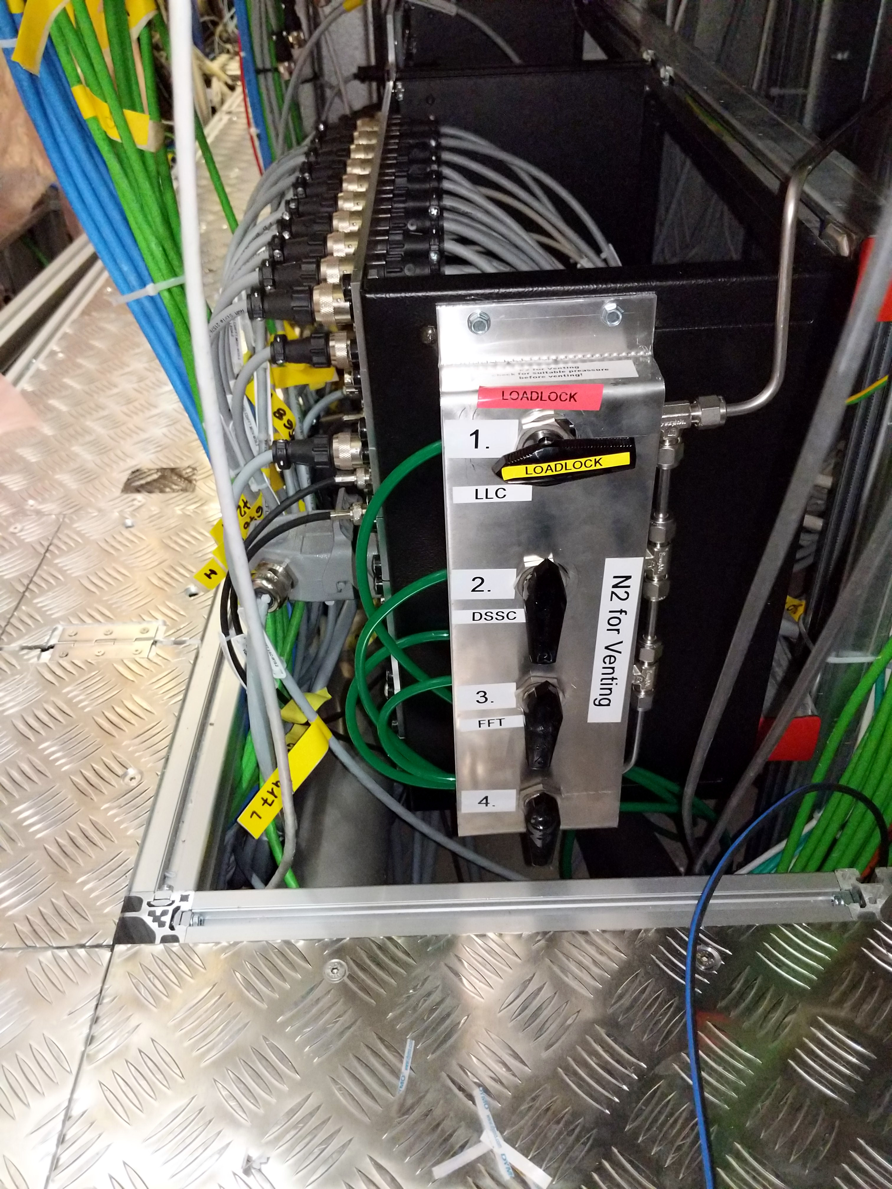
Then open the N2 line for the load lock on the wall. Regulate the pressure to hear audible gas flow sound.
The venting of the load lock through the turbo is automatic and loud.
Pumping down
Make sure the Load Lock doors are all closed.
-
Close the venting N2 line at the wall.
If the venting of the Load Lock was done less than 5 min ago, one has to start the turbo pump again to close the venting valve on the turbo.
-
Open all roughing valve on the TRANSFER_VAC scene from LOOP11.
Start the turbo pump at the controller on the floor in front of the LIN-DPS.
Load lock is pumped down when the pressure is ~3e-6 mbar.
Transferring a sample card out of the FFT
Make sure the transfer arm is free of any cards.
Move the sample scanner to the transfer position:
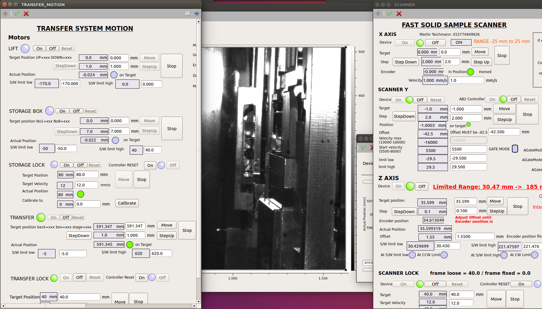
X (mm) Y (mm) Z (mm) 0.0 -1.0 34.6 Check that the pressure in the Load Lock is ~3e-6 mbar and that the FFT is not vented.
Open the gate valve manually between the FFT and the Load lock with a screw driver.

Switch “ON” the TRANSFER arm motor in the TRANSFER_MOTION scene in loop11.

Check that the TRANSFER arm position reads 0mm on the read back value and that the pin is touching the switch on the arm. If not use this value as an offset for the rest of this documentation.
Move the Transfer arm to a position of 350mm
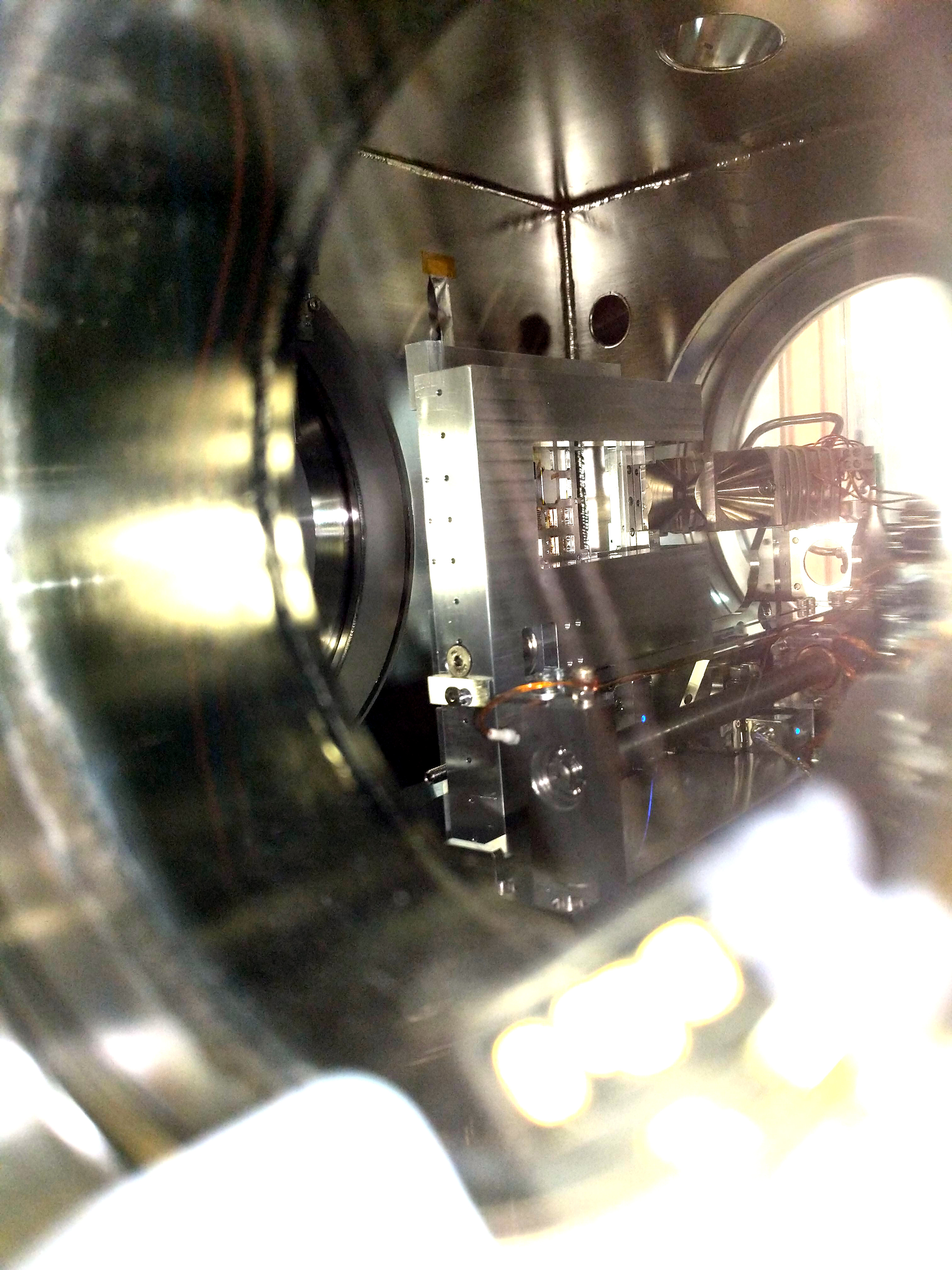
Move in steps of +50mm until you see the arm by looking through the THz incoupling window.
Move in steps of +10 mm until you are near the frame of the sample scanner.
Check visually that the arm is lined up properly.
-
Look from the top with the webcamera1 (TRANSFER_CAMS scene) and approach the arm in 1 mm steps and eventually 0.5 mm until the arm doesn’t move.
Release the scanner lock and then lock the transfer lock. Never ever have both lock in locked status at the same time. Having them both in released state is fine, there is no chance to have the sample card falling off. Apply the “same value” policy in changing the lock values.
Lock status Transfer Lock Scanner Lock Locked 40 0 Released 0 40 Slowly pull back in steps of 0.5 mm the transfer arm and check that the sample card is moving. There is a backlash of 2mm during which the transfer arm doesn’t move.
Slowly move back in steps of 10mm until the card is out of the sample scanner.
-
Move the transfer arm to 0 mm and check that the pin is touching the switch on the arm.
Close the gate valve between Load Lock and FFT.
Transfering a sample card to the FFT
Make sure the transfer arm has a card on it and that the FFT Sample scanner is free of any cards.
Move the sample scanner to the transfer position LLC_transfer_position.
Check that the pressure in the Load Lock is ~3e-6 mbar and that the FFT is not vented.
Open the gate valve manually between the FFT and the Load lock with a screw driver.
-
Switch on the TRANSFER arm motor in the TRANSFER_MOTION scene in LOOP11.
-
Check that the TRANSFER arm position reads 0mm on the read back value and that the pin is touching the switch on the arm. If not use this value as an offset for the rest of this documentation.
Move the Transfer arm to a position of 350mm.
-
Move in steps of +50mm until you see the card by looking through the THz incoupling window.
Move in steps of +10 mm until you are near the frame of the sample scanner.
Check visually that the arm is lined up properly.
-
Look from the top with the webcamera1 (TRANSFER_CAMS scene) and approach the cards in 5mm steps until you are close to the PEEK rail.
Continue in steps of 1mm and check that the card lines up in the PEEK rail.
Adjust the webcamera1 (TRANSFER_CAMS scene) to look at the start of the second PEEK rail and approach it in steps of 5mm and then slowly in 1mm steps. Sample Scanner Y might need to be adjusted if the cards doesn’t slide properly in the second PEEK rail.
Continue in steps of 5mm until you are close to 585mm.
Continue in steps of 0.5 mm until the arm doesn’t move.
Release the transfer arm lock and then lock the scanner lock. Never ever have both lock in locked status at the same time. Having them both in released state is fine, there is no chance to have the sample card falling off. Apply the “same value” policy in changing the lock values LLC_transfer_lock.
Slowly pull back in steps of 0.5 mm the transfer arm and check that the sample card is not moving. There is a backlash of 2mm during which the transfer arm doesn’t move.
Slowly move back in steps of 10mm until the arm is out of the sample scanner.
-
Move the transfer arm to 0 mm and check that the pin is touching the switch on the arm.
Close the gate valve between Load Lock and FFT.
Instructions based on elog 4083.