MPOD MCPs

Ramping up:

SCS_MPOD_SIMPLE 
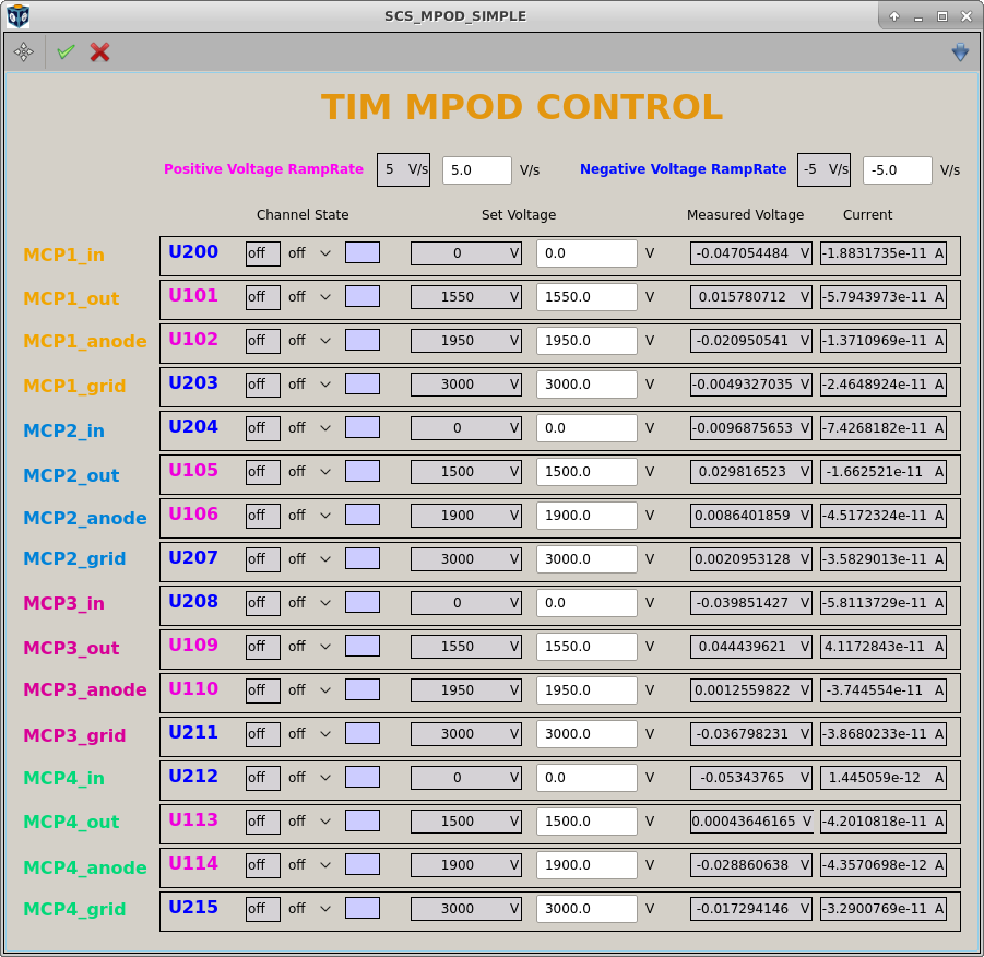
Open the project “SCS_FAST_ADC” and the scene “SCS_MPOD_SIMPLE”, it controls the voltages.
SCS_UTC1-MCP-ADC-1 
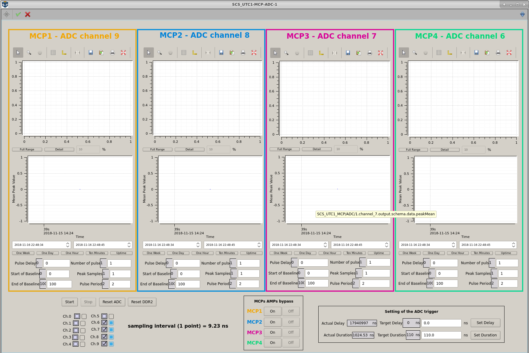
Open the scene “SCS_UTC1-MCP-ADC-1”, here you can see the MCP signals read by digitizer (the old one). Start the digitizer by clicking button in the scene.
TIM-IMAGERCAMERA 
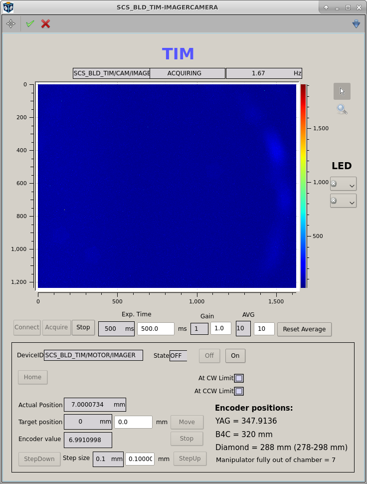
Move diamond into the beam (in the TIM imager camera scene)
SCS_MPOD_SIMPLE Switch all voltage channels ON
SCS_MPOD_SIMPLE Set the “*_anode” voltages to 400 V. After this, when changing the “*_out” voltages, you will always have to keep the difference between the “*_anode” and *_out” voltages at this level, i.e. changing them simultaneously
SCS_MPOD_SIMPLE Set the “*_out” voltages to 1700 V and “*_anode” voltages to 1700+400=2100 V.
SCS_MPOD_SIMPLE Set the “*_grid” voltages to 3000-3500 V to repel the photoelectrons.
SCS_MPOD_SIMPLE Look how your signal looks like. If it saturates anywhere, decrease the “*_out” and “*_anode” voltges; if it is very weak, increase “*_out” and “*_anode”. Maximum allowed “*_out” voltage is 2400 V. In my experience, “*_out” around 1500 to 1700 V should be OK for the 1st order grating mode and the signal will saturate already at 1800-1900 V
SCS_UTC1-MCP-ADC-1 If the signal is too strong and oversaturates, you can also switch off the amplification by setting it into bypass.

Ramping down:

SCS_MPOD_SIMPLE When finished working, ramp down the voltages, switch off the high voltage channels.

General things:

  • Wen you set the voltages, it is better to enter all the new values for different channels and then click the green check mark in the toolbar once.
  • The group “SCS_ADC_1” in DAQ contains the digitizer output and HV MPOD settings. Use it to record the data into DAQ.
  • Look that the voltage ramping rates are not higher than 7 V/s. The rate 5 V/s should be OK. The scene SCS_MPOD_SIMPLE and HV device in Karabo refresh very slowly. If you entered some change and don’t see it - it already happens in reality, but in Karabo you will see the refreshing in few seconds.
  • The MCP signal will look like the sharp negative peak and the broad positive part. We don’t know yet, which of them is more important. But try to make none of them saturating.
  • MCP2 is our best MCP it looks straight at the diamond. MCP1 and 3 look an angle ~ 45 deg. MCP4 is on the back of a chamber at a very grazing angle from the diamond - you will see almost no signal at it.

Based on elog_1364.