How to
There is a XGM manual for operating the XGM written by the XPD group. Of particular importance is the Chapter 7 that documents what is saved by the DAQ (absolutely calibrated pulse energy *photonFlux* in micro Joule and uncalibrated pulse resolved *intensitySa3TD*).
There are also specific HAMP instructions for XGM HAMP operation written by the XPD group.
Startup XGMD
In case the SCS XGMD high voltages are off and need to be ramped up, typically after a HV inhibit event such as shown in XGM_HV_control, the following procedure (from elog_795) can be follow if one is certain that the reason for the HV inhibit as been resolved and cleared:
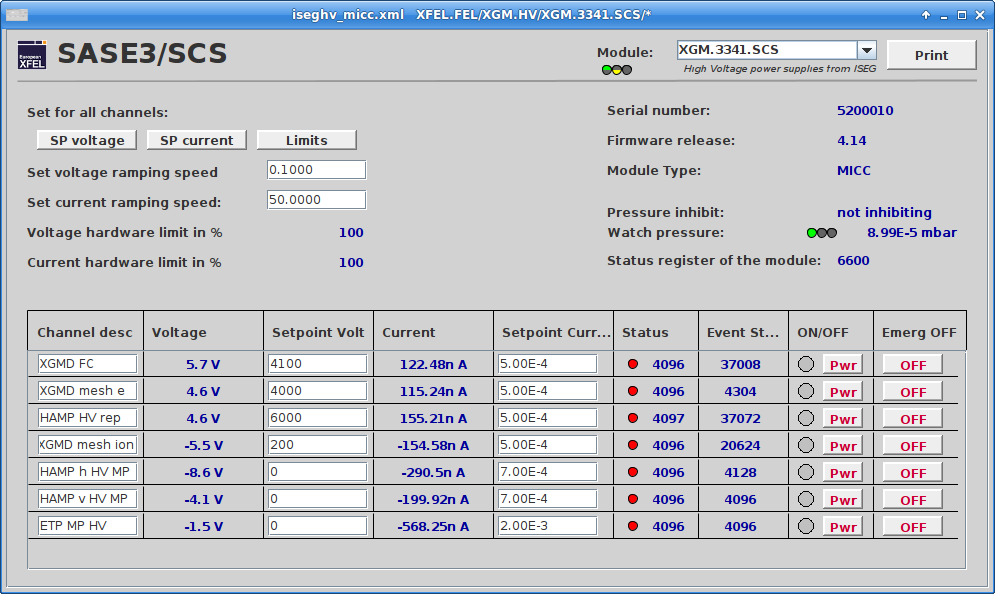
SCS XGM 3341 HV DOOCS control scene with the HV off after a HV inhibit event. From elog_794.
Remove the reason for the HV inhibit from Karabo side
Select the SCS XGM 3341 HV control panel from DOOCS.
Check that the ramping speed for all HVs is already set to 0.1 (keep it there)
Check that the HV setpoint are:
Channel Voltage (V) XGMD FC 4100 XGMD mesh e 4000 V XGMD mesh i 200 V Note that while the “XGMD mesh i” is set at + 200 V, the module (and read-back) is -200 V.
Click ON “Pwr” for all 3 channels simultaneously and they will ramp up again at the correct ramping speed.
Check that the current stays below microAmps. Ramping influences the ion signal, so wait a few minutes and then PHOTONFLUX is reliable again
Note: Please ramp up FC and mesh e simultaneously, because both plates are close by in the vacuum and we want to avoid any change for sparking.
Note: The XGMD voltages above are suitable to separate the photo-ions from the photo-electrons for all SASE3 photon energies.
Startup HAMP
This section is a summary of what is described in the HAMP instructions.
- From the DOOCS panel, select Photons > XGM Overview. Select then the SASE3/SCS XGM.
- Go to ADC ranges to open the panel below:
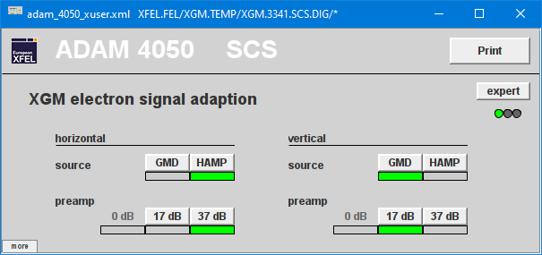
Range selection for HAMP
- Choose HAMP as “horizontal source”. This source is shown as pulse-resolved signal on the SASE viewer window.
- Choose 37 dB. Never choose the hidden 0 dB (we rather kill the amplifiers than the very expensive and special ADC boards)
- Open the HV Control panel
- Power up the two channels HAMP HV rep and HAMP-h HV MP
- Ramp HAMP HV rep to 6000 V in 2 steps (3000 V, then 6000 V)
- Ramp up HAMP h HV to 100 V, 500 V, 1000 V, then steps of + 100 V. Max. 2000 V!
- Open the Pulse-resolved signal RAW-h panel and observe the signal.
- Activate Show persistence by right-clicking on the X-axis
- A good signal is typically obtained when the peak envelope is around -2 mV. Maximum recommended by XPD is -7 mV
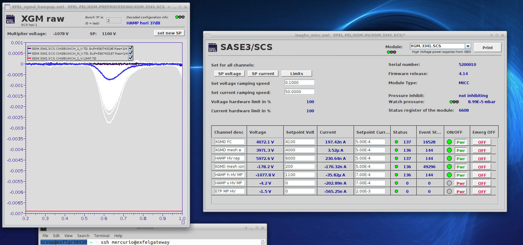
Example of HAMP settings (from elog_937).
Warning
The photon flux must be carefully monitored when the HAMP is on, especially when operating the GATT. The HAMP h HV must be adjusted to avoid saturation and potential damage of the detector.
Calibration
There is a tool to easily calibrate the fast to the slow data as shown in XGM_calibration.
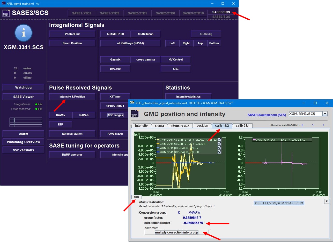
SCS XGM calibration panel in DOOCS. From elog_749.
- Click on “Intensity&Position”, select “calib 1&2”, and click on “more”.
- There you find the “correction factor”. If you click on “multiply correction into group” both fast TD channels will be calibrated to photonflux.
Note: Please do not forget that this calibration is only correct if the majority of pulses are lasing in SASE3 (more dedicated than suppressed pulses).
Note: Please wait until the offered “correction factor” moves side-wards and is stable before you calibrate.
HAMP pulse integration
If the HAMP pulse integration needs to be adjusted:
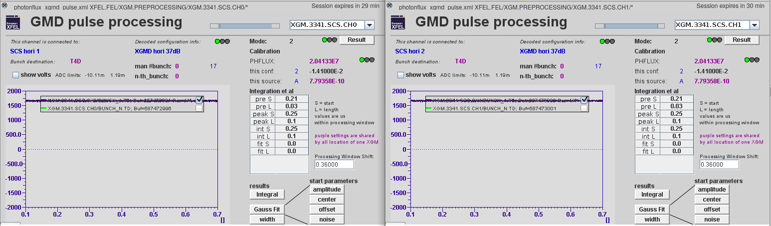
HAMP pulse integration control panel in DOOCS.
Open the “Preprocessing” DOOCS control for the SCS XGM 3341 CH0 and CH1 as shown in HAMP_integration.
In mode 2 the pulse integration is performed. The used parameters and descriptions are:
parameter name description preS start of background preL length of background intS start of integration intL length of integration
Note: Both CH0 and CH1 must have identical parameters sets. The pulse integral from CH0 and CH1 are summed up together before calibration to photonflux or saving in DAQ under “intensityTD”.