Reflectometer stage
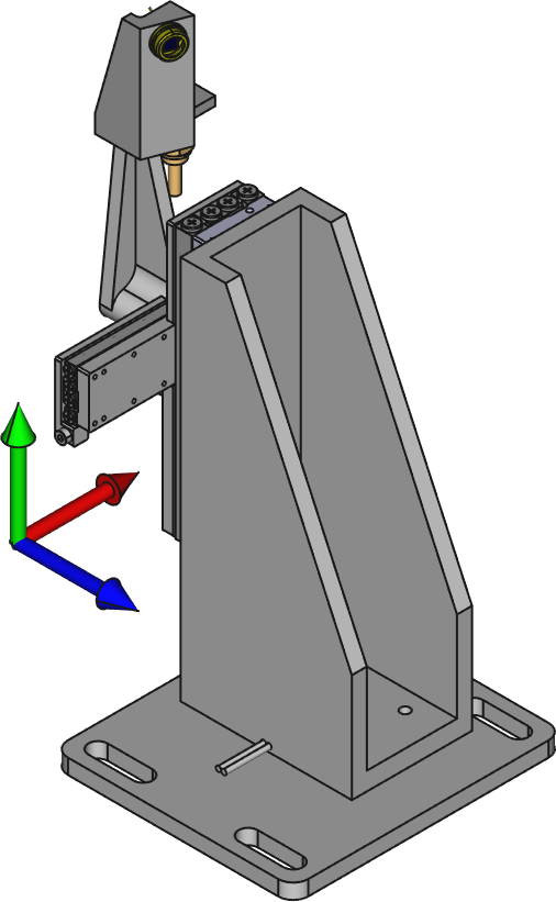
Drawing of the reflectometer stage with the hutch reference axes
The reflectometer diode can be moved on the reflected optical beam with the reflectometer stage shown in reflectometer-stage-motor-direction. The positive motor direction is given in the table below.
Motor table:
| Stage Motor | Positive motion |
|---|---|
| 5 | -Y |
| 6 | -X |
Laser in-coupling and sample blades
To get the optical laser reflected on the reflectometer diode, it is necessary to have an angled blade on the sample card. Depending on the sample position (SAM_Z) the blade angle will be different as shown in LIN_in-coupling_blade for LIN in-coupling and in THz_in-coupling_blade for THz stage in-coupling, as calculated in elog1550.
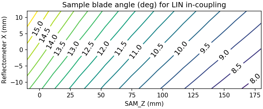
Blade angles for LIN in-coupling geometry as function of sample Z
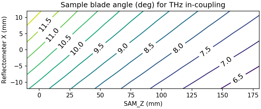
Blade angles for THz stage in-coupling geometry as function of sample Z