Venting and Pumping the FFT Chamber
Venting
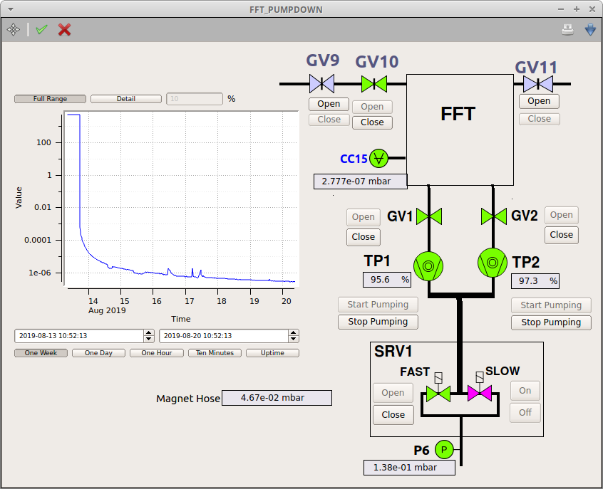
Close the SRV “FAST” and “SLOW” valves on the FFT_PUMPDOWN scene. Then stop both turbo pumps TP1 and TP2. Prevent GV1 and GV2 from closing while venting by disabeling all interlocks in their respective karabo device. If not there is a major risk of shock venting the turbo pump once we tried to pump down the FFT again as with GV1 and GV2 closed, only the FFT vessel will be vented while the TP1 and TP2 will be under rough static vacuum.
Disconnect both GV9 and GV11 control cables. GV10 is to be left open at all time.
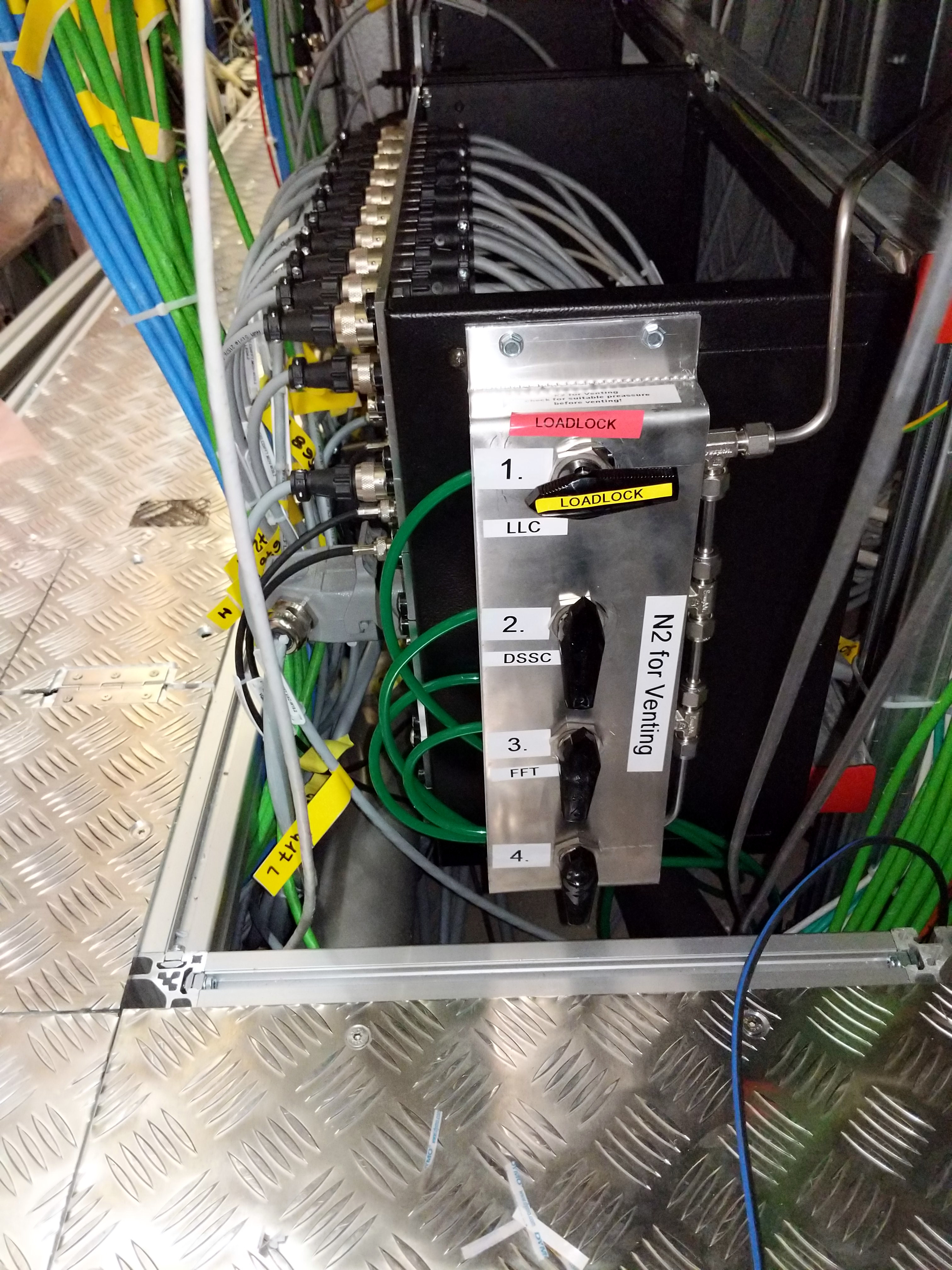
Open the N2 line for FFT and regulate the flow.
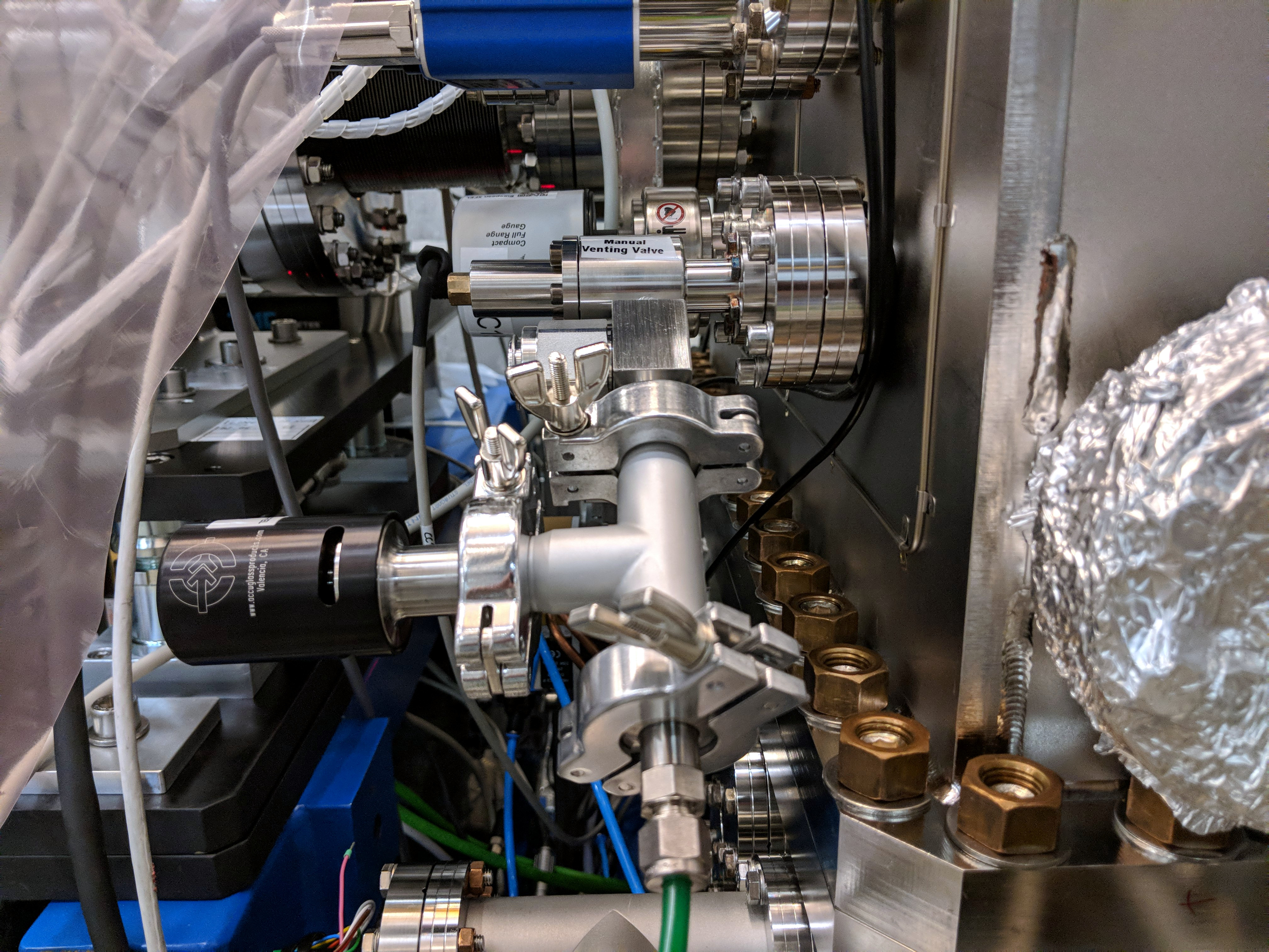
Make sure the over-pressure valve make sound and slowly open the manual venting valve upstream the FFT until the pressure in the chamber is 1e-2 mbar.
-
Wait for both TP1 and TP2 to spin down.
-
When the pressure is in the few mbar, the venting valve can be opened fully. The complete venting takes a long time, about 30min, so be patient.
-
Close both GV1 and GV2 on top of the turbo pumps.
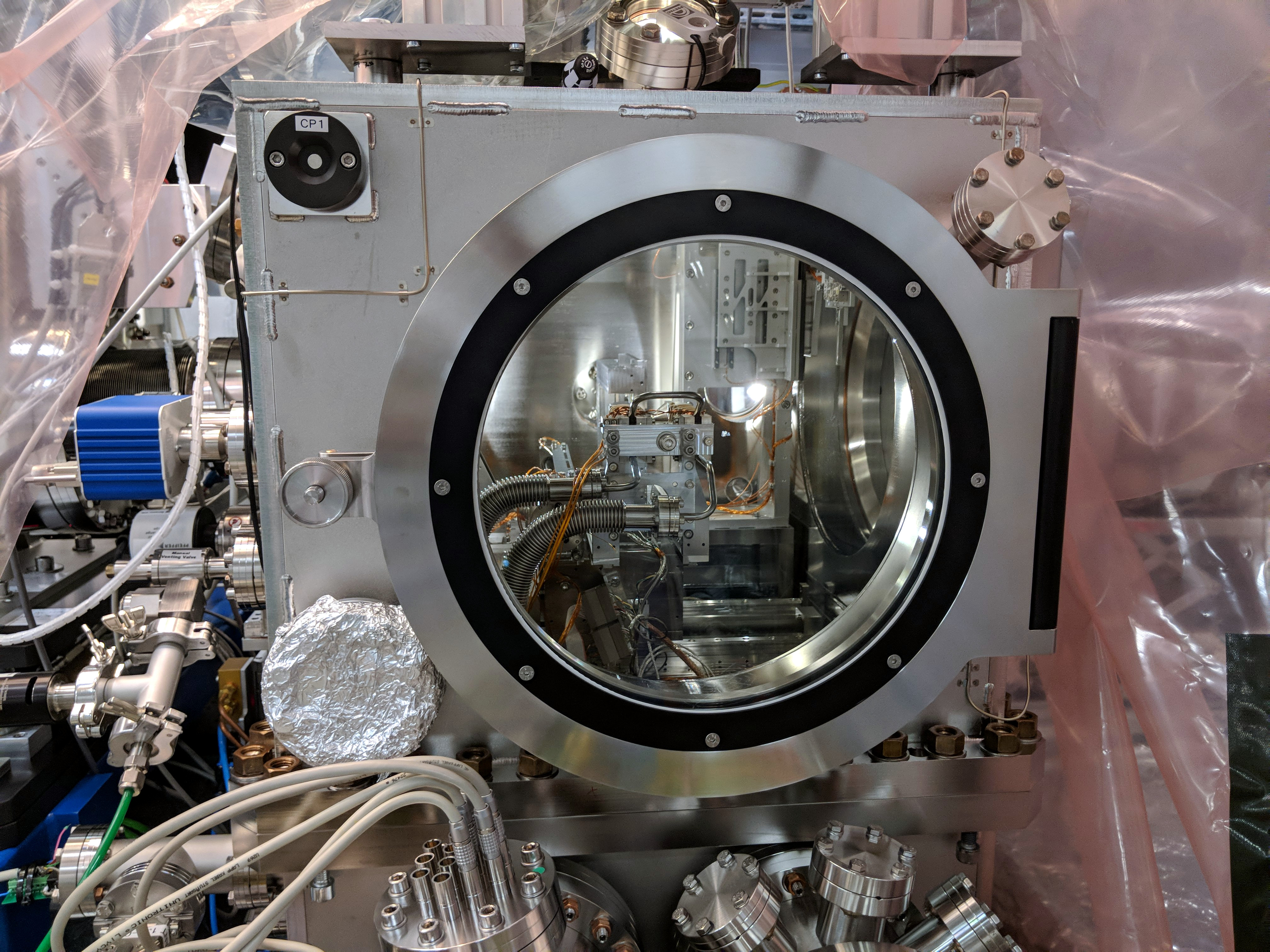
Open the quick access door with a clean tent installed around it.
Close venting valve and the N2 line.
Pumping down
-
Close the quick access door and the venting valve.
-
Open GV1 and GV2 on top of each turbo pumps. Make sure GV10 is still open.
Open the SRV valve “SLOW” to begin pumping down the FFT slowly so that filters don’t get damaged.
Once the pressure is in few tens mbars, open the SRV “FAST”. The SRV “SLOW” will close via automatically via interlock.
-
Once the pressure is less than 2 mbar, start up TP1 and TP2.
Make sure the quick access door is properly closed by tightening the screw.
The pressure should reach 2e-3 mbar quite fast and then plateau for few minutes as water desorb and then slowly reduces.
Re-enable GV1 and GV2 interlocks that were disabled during venting.
Reconnect both GV9 and GV11 control cables when the pressure is good enough that the gate valves can be opened.