BOZ alignment
Collimate FEL Defocus KB mirrors by sending both HFM and VFM benders to CW limit switches (largest position, close to 200 mm). This can take ~30 min, so plan ahead.
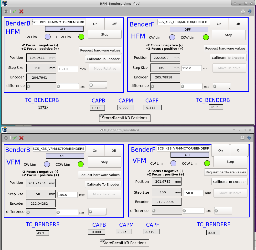
KB mirrors fully defocused (from elog 2078).
Image FEL beam at sample position Switch off all LEDs to maximize the camera sensitivity for low intensity beams. This avoids using high GATT transmission on the zone plate unnecessarily. Look at the FEL (SA3 mono 1st or 2nd order) on pBN at the sample position, with typically 2 - 10% GATT transmission. The beam should look like this:

1st order of FEL on pBN at the sample position with defocused KB mirrors, from elog 2497/36.
Aperture the FEL beam Aperture the FEL beam upstream of the BOZ with the guard stage to the exact dimension of one BOZ optic. One way is to find the half-clipping position of each four blades, and then opening by half the BOZ optics size. A typical BOZ optic size is HxV=0.8mmx1.0mm.
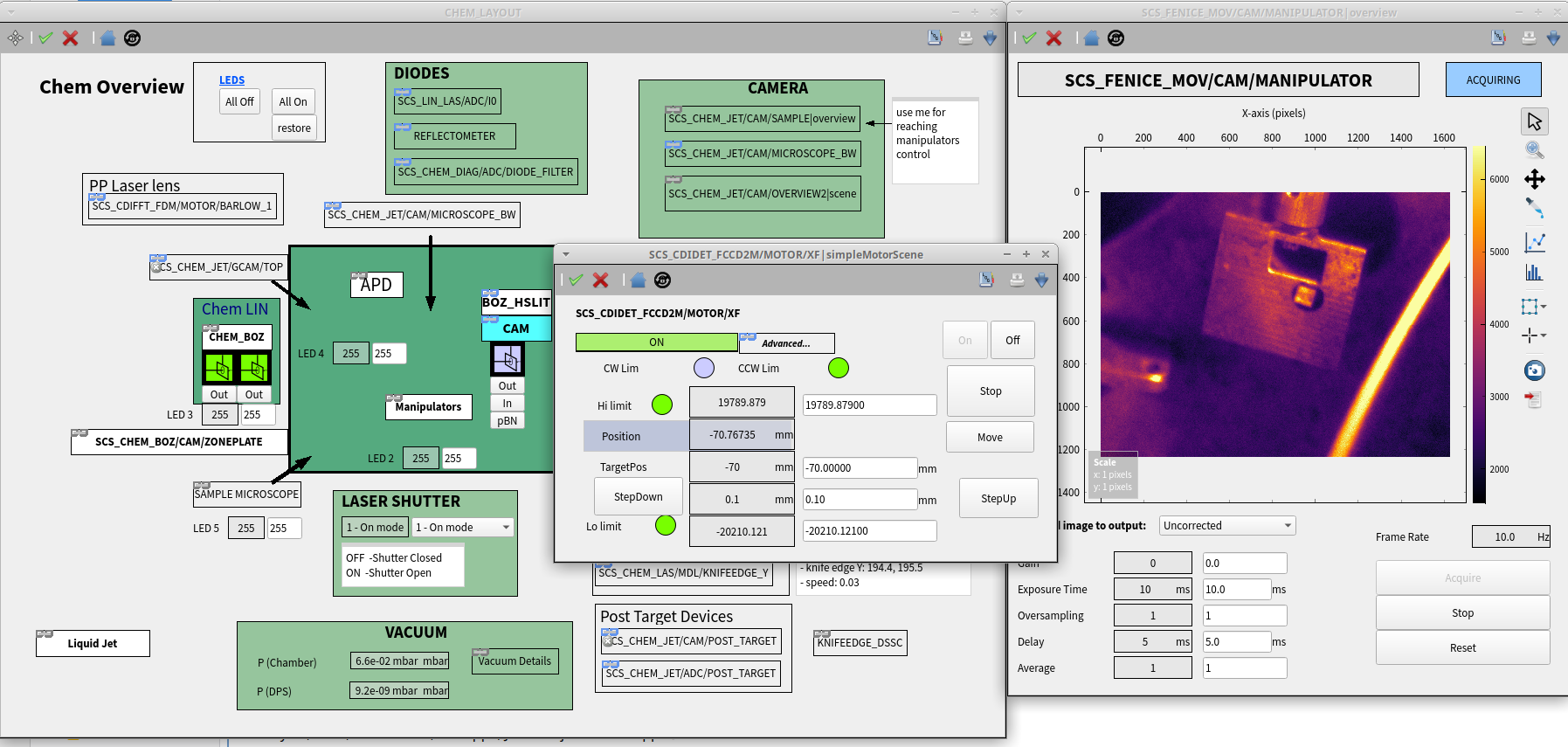
Rough BOZ alignment Set BOZ Z=0 and use the BOZ design photon energy. Use the BOZ Point&Click scene and the X and Y BOZ motors to roughly align the desired BOZ in the apertured FEL beam. You should see 3 focused spots appearing above. Move in X to center the middle spot to the middle of the direct beam. Move in Y to change the distance and slightly separate the middle beam and the direct beam.
Refined BOZ alignment with DSSC Lower the GATT transmission (~0.5% with mono in 1st order, ~10% in 2nd order) and look at the DSSC. The 3 beams should be centered on the inner sensor of the Q4M4 ladder. If not, either the DSSC is not well centered or the BOZ is not well centered on the FEL beam, or the FEL beam is not well aligned. Once everything is aligned, use the guard stage aperture to separate the 3 beams on the DSSC.
With CHEM, it is also possible to rotate the BOZ around Z so that the 3 beams are not titled with respect to the DSSC sensor. Typical tilt angle is ~1deg.
DSSC signal from BOZ setup, from elog 2609/30. The gradient of intensity from left to right is due to the BOZ not being properly aligned with the FEL beam laterally.
Harmonic suppression 2nd harmonic light from the undulator is a problem for the BOZ setup and should be supressed. This radiation is visible as 3 additional beams of half the size and at half the distance from the direct beam which overlap with the fundamental light beams.
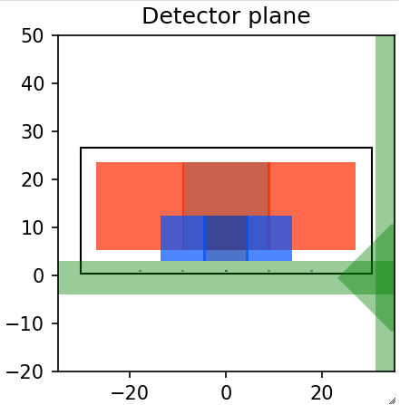
BOZ beam on DSSC sensor. Orange beams at from the fundamental and blue are from the second harmonic undulator radiation.
To supress this radiation, we have two options:
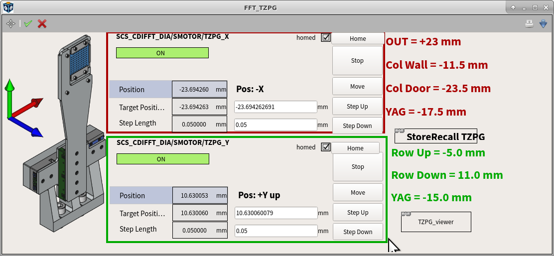
- in the FFT chamber, we use the sample bottom edge to clip these beams
- in the CHEM chamber, we have a dedicated slit after the liquid jet sample to clip the unwanted ratiation
Setup BOZ-mono sync Follow self-explanatory instructions on the scene to enable combined motion of the BOZ and the photon energy so the beam pointing and focusing is stabilized.
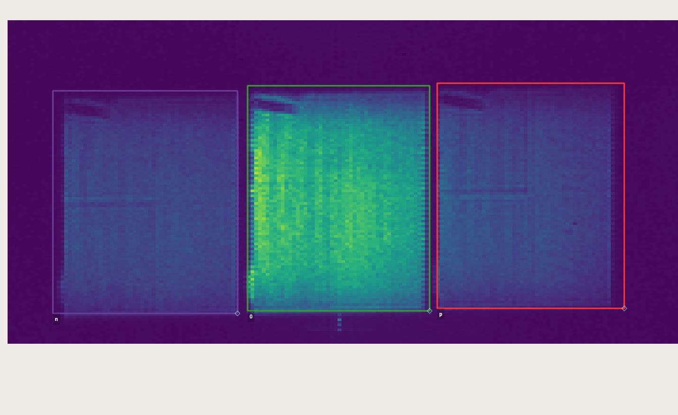
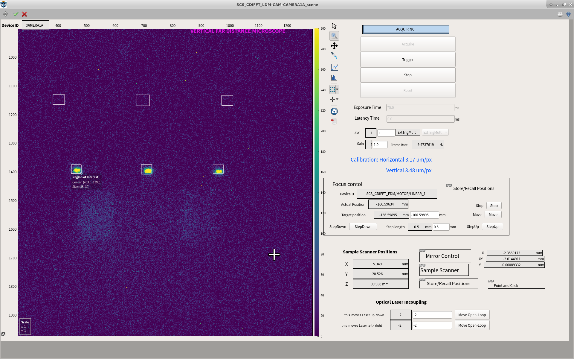
Go back to the pBN and mark the position of the beam with 3 rectangles on the pBN.
To save these ROIs, change the scene to design mode (top left button), right clik on the image widget and select ImageGraph: Properties > Set ROI and Aux, and save the Karabo project.
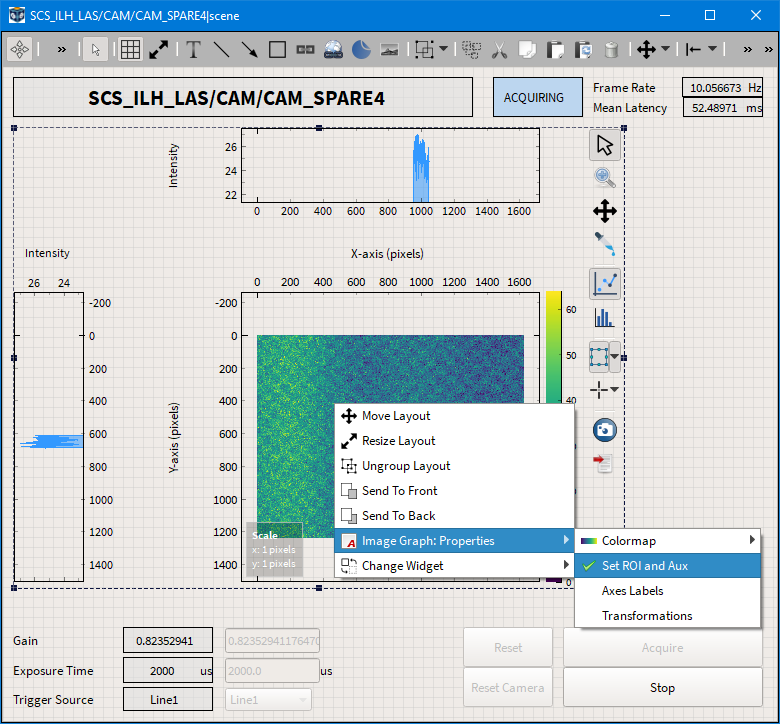
Example how to save the ROI and crosses on a scene for future reference.