Synchronization
When talking about the laser synchronization we mean the link between the timing system and the oszillator for the PP laser. The performance of this link is what is quantified by the time jitter presented in the karabo-guis and doocs. This is only a part of the overall time jitter at the sample.
RF sync
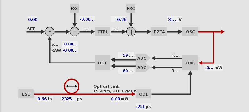
The schematics of the rf synchronization mode is presented below. It is at its core a control loop acting on the oszillator cavity (to do). A portion of the oszillator output is picked up by a photodiode. This signal is down converted to a frequency adequate to be digitized by an ADC. Undersampling of the resulting signal leads to the appearance of an aliased signal at the difference frequency. A variation of the phase (location of the signal in f-space) is then added to the setpoint accordingly.
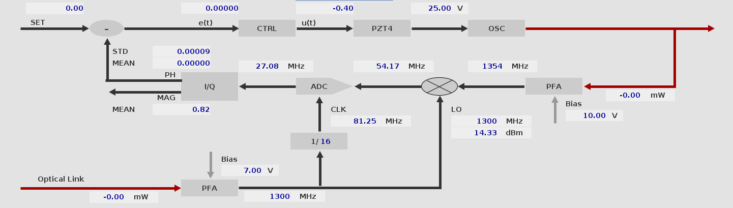
Schematics of the synchronization in rf mode.
Note: Adding/removing phase basically pushes/pulls the oszillator. Therefore, by adding a certain amount of phase we can adjust the time reference by a arbitrary delay.