How to find spatial and temporal overlap
| Author: | Laurent Mercadier <laurent.mercadier@xfel.eu>, Rafael Gort, Robert Carley <robert.carley@xfel.eu> |
|---|---|
| Date: | 2021-12-06 |
| Revision: | Revision: 2 |
Spatial overlap
Spatial overlap between the optical laser beam and the FEL beam is usually achieved on a pBN or YAG sample mounted on the sample holder of the interaction chamber. The aim is to first locate the position of the FEL beam, mark it with a cross, then switch to the optical laser and steer the appropriate in-vacuum mirror to overlap its position with that of the FEL.

X-ray beam on pBN

Optical laser on pBN
Warning
The power of the laser must be attenuated to avoid damage to the pBN! Typically, we start with 1 pulse, 0% power of the HWP and ND 4 on the Filterwheel and gradually increase the number of pulses or change the ND filter until the beam becomes visible.
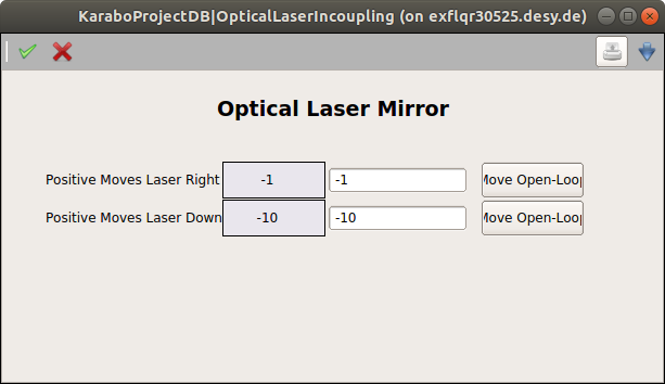
With LIN in-coupling
When the optical laser is brought to the experimental chamber via the LIN section, the LIN in-vacuum mirror is the one to be steered to achieve overlap. The mirror mount has two Smaract piezo motors for pitch (Y movement) and yaw (X movement) that do not have encoders and can only move in open-loop. A relative movement of amplitude 10 will typically offset the beam by ~100s of micrometers at the sample position.
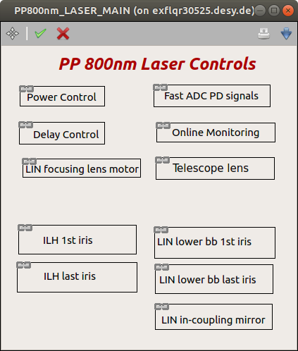
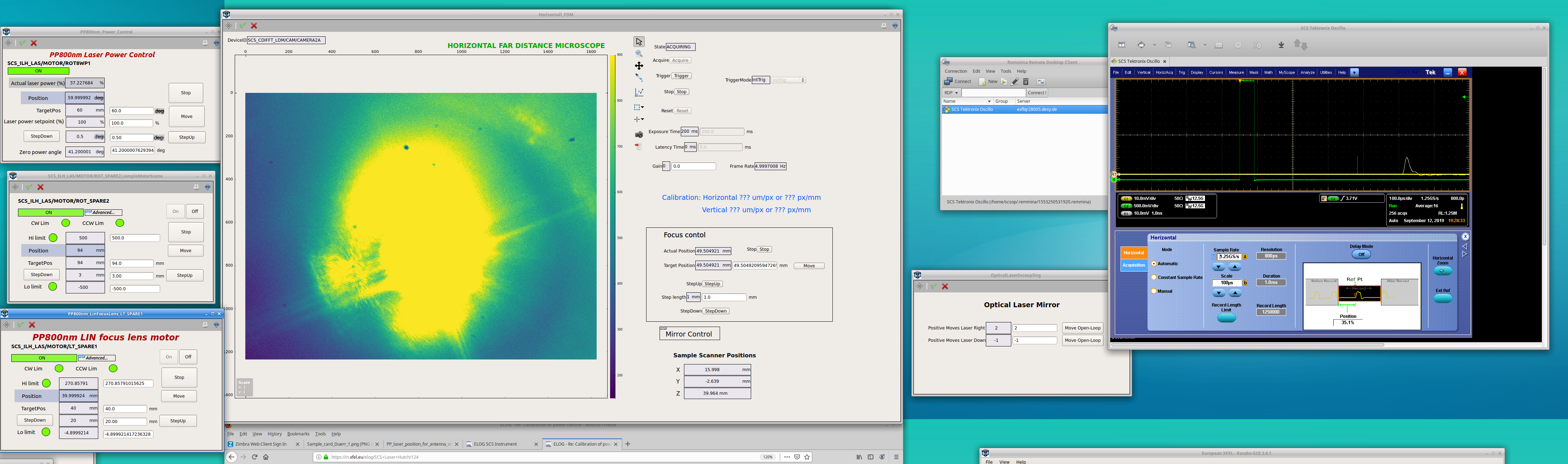
The corresponding scene, named OpticalLaserIncoupling can be found in the section Beam Alignment of the main PP laser scene, under the name LIN in-coupling mirror. The motors can also be directly controlled from the Vertical FDM scene when using the FFT.
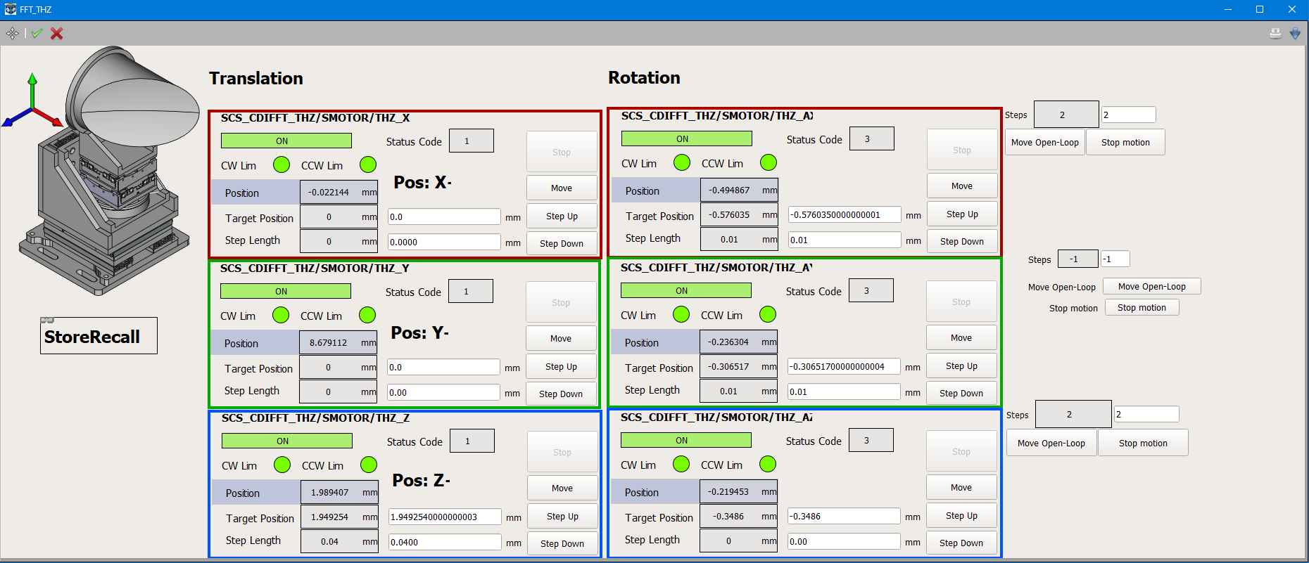
With THz in-coupling (FFT)
When the optical laser is brought to the experimental chamber via the THz in-coupling of the FFT chamber, the THz in-vacuum mirror is the one to be steered to achieve overlap. The mirror mount has six degrees of freedom and the corresponding scene can be found in the FFT link scene under the name THz stage.
Coarse timing (FFT)
After finding spatial overlap at the sample position, coarse temporal overlap is achieved by overlapping the signals of the FEL and the OL from an antenna on the diagnostic stage using an oscilloscope (Tektronix DPO 71254C, 12.5 GHz bandwidth). Once the overlap is found, the synchronization of the PP laser with the XFEL timing must be locked: either via RF (jitter of ~50 fs) or optically (jitter of ~5 fs). See Synchronization for more details.
The FEL and OL are not colinear, therefore they do not overlap at the diagnostic stage position. Consequently, the two signals must be recorded one after the other after adjustment of the antenna position. The difference in time arrival at the two positions is way below the accuracy of coarse timing determnination.
The antenna is labelled L for left, and it is connected to feedthrough #1 of the left side CF 63 feedthrough (see elog 987 for details). An SMA cable goes from the feedthrough to the user chicane in the control room. It is connected to the oscilloscope (usually on Channel 1).
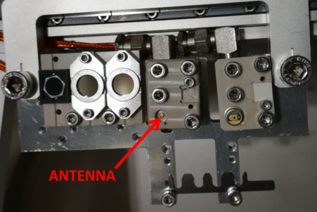
Position of antenna on FFT diagnostic stage, photo from Elog 2736.
The scope is triggered via the Karabo device SCS_CR_SYS/TSYS/SCOPE, which controls the trigger from port 108.885 of PPG207, with ETA box QR30351. The scope can be remote-controlled using Remmina on all the machines of the control room (see Oscilloscope).
Step-by-step guide to coarse timing
The sequence for finding coarse timing is the following:
Set GATT to 1% in 1st order, 1 pulse. The attenuation depends on the focusing conditions, to be adjusted with scope signal.
Insert the diagnostic stage at the antenna position for FEL (usually using Store/Recall device).
Choose the scope trigger source to be the antenna signal to find the FEL pulse.
Change the trigger source to the 10 Hz trigger and adjust its delay in Karabo to be as close as possible to the FEL (within 2 ns). Averaging over 16 traces usually helps.
Save and overlay a reference trace on the scope.
Block the FEL.
Move the OL focusing lens as far downstream as possible. The motor depends on which laser in-coupling is set.
Move the diagnostic stage to the antenna position for OL. This position can be found using an alignment laser and the overview camera, for instance.
Remove all ND filters in the OL path. Obtaining a signal on the antenna usually requires a significant amount of pulse energy.
Set PP laser to 1 pulse, 1% power (if TOPAS, use appropriate power control). Depending on the wavelength and power, the laser on the antenna can be seen with the overview camera. The FSSS Z position needs to be upstream enough (Z < 20 mm) not to obstruct the view. If Z movement is necessary, one may need to also adjust the FSSS horizontally to pass through the hole in the sample cart.

FFT Overview camera: single PP laser pulse, 400 nm, irradiating the antenna with 75% power.
Change the trigger source to the antenna signal.
Ramp up the power of the laser until a signal is found.
Fine-tune the diagnostic stage position to maximize the signal.
Change the trigger source back to the 10 Hz trigger. The aim is now to overlap the OL signal to the reference by adjusting the PP laser timing.
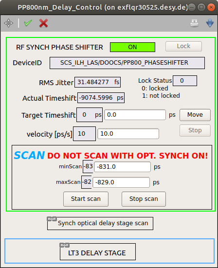
Open the scene Timing-changes-800nm in the Instrument Timing and Status project of the LA3 topic:
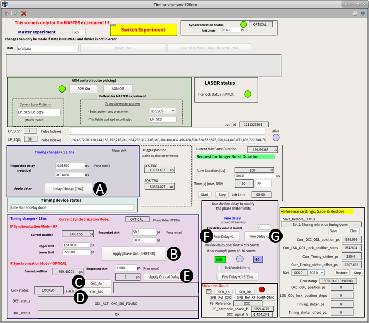
From this scene, it is possible to:
- change the PP laser trigger delay (A) for coarse timing changes of > 18.5 ns
- in RF lock mode, change the phase shifter delay for timing changes of 18 ns or less (down to fs)
- enable the optical synchronization
- disable the optical synchronization
- in OPTICAL lock mode, change the synch delay line for timing changes of 1 ns or less (down to fs)
- and G. in RF mode, if necessary, adjust the delay limits of the phase shifter
In the top right corner, the synchronization status (RF or OPTICAL) is displayed (green = ON, dark blue = OFF).
- Make sure that SCS is the MASTER experiment. If not, open the scene Switch Experiment and make the change.
Warning
If SCS is not the MASTER experiment, do not use this scene!
Navigate through the following diagram. The actions to take A - G refer to the Karabo scene from point 15.

Note
It can take up to several minutes to enable optical synchronization.
After this procedure, the final signal on the scope should be similar to this:

10 Hz trigger (channel 4, green), FEL reference (white) and OL signal (yellow)
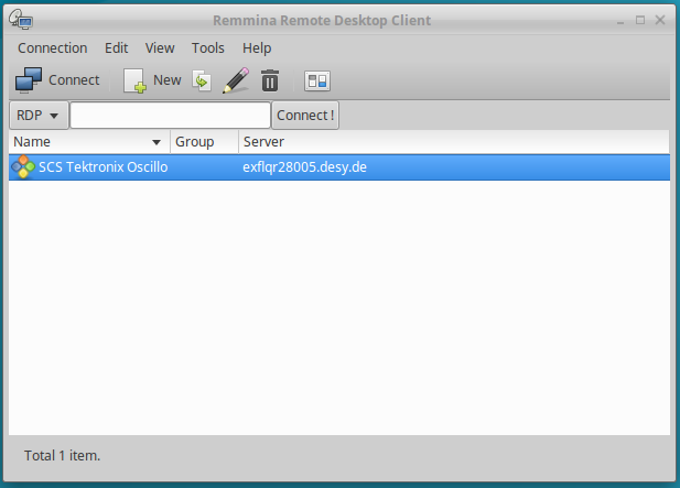
Oscilloscope
The oscilloscope in the control room can be remote controlled. In a terminal, type remmina to start Remmina RDP, and choose SCS Tektronix Ocsillo to start the connection:
If this connection does not exist, create a new one with:
- username: Tek_Local_Admin
- pasword: 12345
- workgroup: WORKGROUP
- hostname: exflqr28005.desy.de
Fine timing (FFT)
To do.
Older documentation (to be sorted)
General information
In the SCS topic you need:
In project Loop13, the scene:
PP-laser main scene
In project Main the scenes for the FDMs the sample scanner, the diagnostic stage and the reflectometer stage.
In project SCS_PPL_PATTERN the scenes for arbitrary and periodic patterns.

Arbitrary laser pattern scene

Periodic laser pattern scene
Within the LA3 topic available through the gui server running on exflcon132 we need:
- In the project ‘Instrument Timing and Status’ the scenes:

Timing main scene
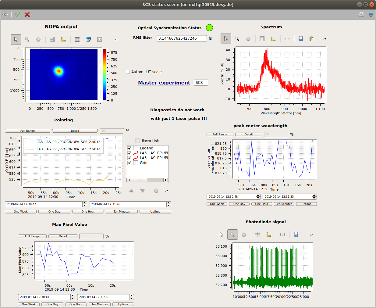
Timing SCS, status scene
Comments
- The karabo devices to change the PP timing and pulse pattern are expert tools. In case you are not sure about the effect of certain changes please ask one of the trained persons. Amongst the things that could happen are:
- loss of information and trigger settings at SCS and possible damage to equipment when using a wrong pulse pattern.
- loss of information and trigger settings at SQS.
- The karabo-server scs_pplPattern is running on the host exflcon146 and can so far only be started by Robert, Laurent or Rafael (can do this remotely). For further information consult the Expert_section.
- It is useful to work on the control room workstation all the way to the left (exflqr30525) because it is the closest to the laser shutter.
Goal
- Align the 800nm path in the ILH.
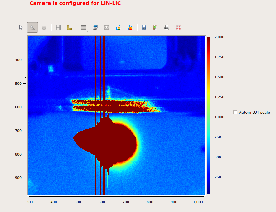
- Bring the Ol-beam into the beamline. We first check the position at the LINLIC.
- Bring the FEL and the OL onto a pBN and overlap the two.
- Monitor the coarse timing with an antenna. Adjust the delay of the OL to match the FEL arrival. For this we will first use the trigger delay (such that the 1. OL pulse appears in a 18ns window around the 1. FEL pulse) and then the RF phase shifter, or the optical delay line from the synchronization unit to overlap the two pulses with an accuracy of ~10ps.
- Fine timing: use the reflection from a SiN membrane to measure a change in OL reflectivity with respect to the Pump-Probe delay. To do so, the FEL acts as the pump, the OL as the probe.
Step by step user manual
1. Align beam in ILH
(see main page)
2. Bring the beam to the hutch
Set the power control unit (L/2 plate and polarizer) to the minimum transmission (0%) and use only 1 pulse at first.

The hutch needs to be searched such that the shutter can be opened from the control room.
Move in the LINLIC imager (use the values indicated in the gui).
Double check the power settings before opening the shutter.
Turn the key on the interlock panel and press the “arm” button.
Open the shutter
At the IN position the FEL should appear on the lower part of the upper imager and the OL will appear on the upper part of the lower imager. Slight deviations from this situation are ok and one can move to the pBN directly. (otherwise consult the expert_section).
Close the shutter again and move the imager out.
3. Coarse timing on antenna
(some points still require more elaborate explanations)
Go to the pBN
Align the beams such that they overlap on the antenna. In FFT the antenna is downstream of the sample, so the OL beam has to be pitched down. Some lateral movement may also be necessary. Use the LIN in-coupling mirror to get the OL beam on the antenna. Its controls can be found in the PP800nm main gui or the vertical FDM scene. The offset depends on the z-position. Have a look at the latest elog entries in case the current z-position has been used before for coarse overlap.

Block both beams
Move the antenna in. (In the FFT the antenna can be seen with the hFDM if the sample is in the upstream position)
open the remote connection to the oscilloscope connected to the antenna (remmina &)
set the FEL to 1% transmission and use 1 pulse
unblock the FEL, find it on the oscilloscope, adjust the transmission, save a waveform
block the FEL again
double check that the OL has relatively low power (start with 0.5% transmission). Make sure nothing is in the way of the OL beam path (an imager ….).
open the shutter. The OL should be visible (cameras, FDMs).
Adjust the position by either moving the antenna, or using the LIN incoupling mirrors.
slowly increase the laser power (normally 2% is enough) while checking the oscilloscope. Use an appropriate time range to do so. (Examples: coarse_timing1, coarse_timing2)
Coarse timing example 1

Coarse timing example 2
- In the next step we use the scene Timing_changes_800nm to find coarse overlap between the FEL and the OL. Different things need to be taken into account:
- If SCS is not the master experiment: Do not use this window!
- Select the pulse pattern LP_SCS. Otherwise the changes entered in the pulse pattern scenes will have no effect.
Independently on whether the PPL is locked optically or in RF, use the trigger delay in Timing_changes_800nm to overlap the two pulses in an 18ns window.
After this you can do finer steps. As stated in the Gui you can use: * The phase shifter in RF sync * The optical delay stage in optical sync.
To switch in between the two modes use the checkbox

How to enable optical lock
(Do not use the LOCK_UNLOCK button. This will disable the synchronization.) When selecting optical lock, a routine in the background tries to find optical lock. This might take several minutes.
** Caution ** with the Timing_changes_800nm scene!!
Timing changes that are less than 18ns but still significant (e.g. 12ns) can cause the optical delay line (ODL) of the cross correltatior (OXC) to reach the end of its travel. To avoid this problem please follow the procedure below:
- Observe the ODL_status during changing ODL position.
- If the ODL_status shows either “SOFTWARE POSITIVE POSITION LIMIT CROSSED (16)” or “SOFTWARE NEGATIVE POSITION LIMIT CROSSED (32)”, it is not possible to move the ODL further.
- In this case, you need to switch to RF synchronization (button OXC_Dis), move the phase shifter (RF), switch back to optical synchronization (button OXC_En), and observer OXC_status.
- When the reference signal is found, you can continue scanning with the ODL.
Please be patient as relocking may take some time.
4. Fine timing
4.1 Fine timing in FFT
(to be updated)
In this section you need:
Gui for RF control

optical sync scene
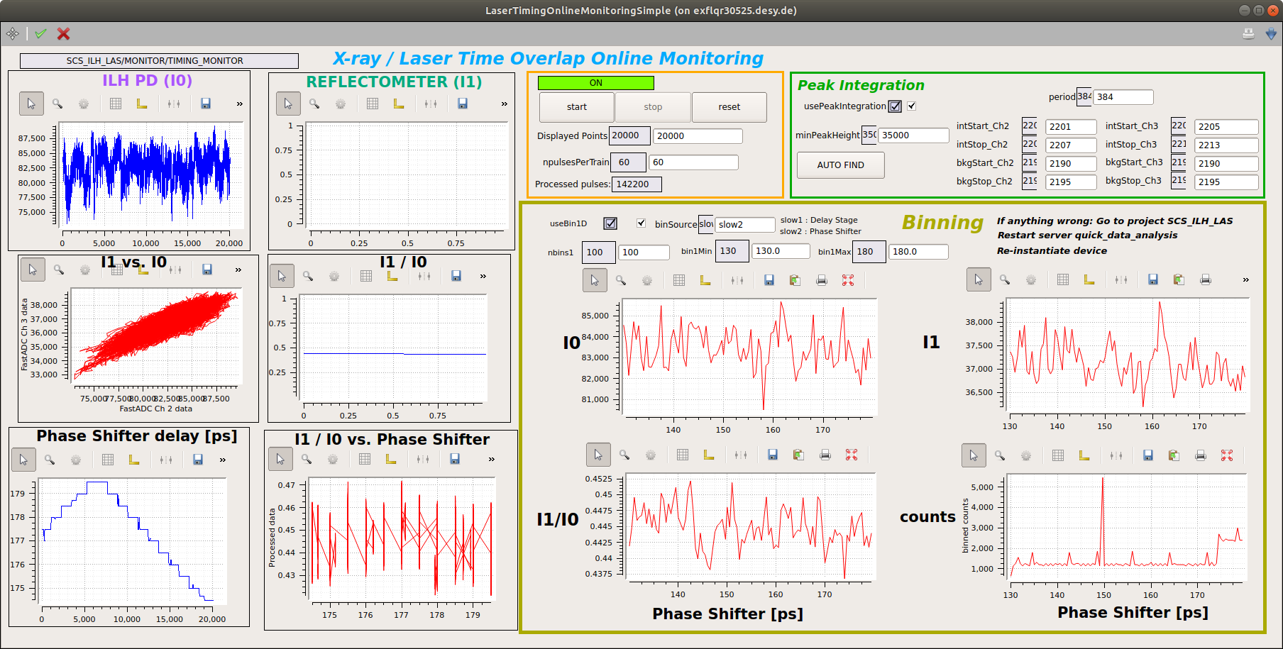
Online monitoring GUI.
Now you can:
block both beams
move back to the sample pBN for spacial overlap (Duerr beamtime, downstream position : X=5.4mm, Y=-2.1mm, Z=213mm).
increase FEL beam size using the KB mirrors (OL_on_pBN_, FEL_on_pBN_), refocus the OL using the lin focusing lens (focus normally around ~150mm).
Optical laser on pBN
X-ray beam on pBN
set the power and number of pulses to an appropriate value for the pBN, and unblock the beams
Adust the overlap using the LIN in-coupling mirror.
Go to the SiN membrane, move the reflectometer in. Look at the latest Elog entries about the reflectometer positions or use the stored values of the corresponding ‘StoreRecallSetting’ karabo device.
set the OL power to 0%
put an 3.5ND apsorption filter into the OL beam path.
open the shutter of the OL
You should now see the reflected signal in the scene for the fast ADCs. The first trace comes from a diode in the laser hutch and measures I0. The second trace is the diode on the reflectometer stage. We normally work with the same number of pulses for the OL and the FEL and as many as possible. Optimize the reflectometer position.
Set the FEL transmission to 50%
Open the online_monitor gui. Enter the number of pulses that you are using. Use the Auto Find functionality. This should automatically set the background and peak positions. Also set appropriate values in the binning section.
set pulse pattern of the OL, FEL (<20 pulses should suffice)
unblock FEL
use RF phase shifter (RF_control), or the delay stage for the optical sync (OCX_control) to vary the pump probe delay. In both cases you find a scanner in the respective gui. Set an appropriate scan range and start the scan.
Start the online monitor tool. In parallel you can record a run with the DAQ.
The displays can be updated by clickin with the middle button from time to time.
4.2 Fine timing in GPC
(to be documented)
Expert section
- Start the pplPattern server
Riccardo’s documentation can be found in readthedocs (pplPattern). To start the server you (Laurent, Robert, Rafael) have to login to exflcon146 or your gateway account and start it by typing:
( echo your_user_name | nohup ./startPplPatternServer_SCS.sh ) &
or on the gateway: . /opt/karabo/laser/startPplPatternServer_SCS.sh
This will start the device server in the SCS topic and dump the output to nohup.out. You can close the terminal after this. The newest version of the script can be found on the gateway in /opt/karabo/laser/ .